
Installation Guide

507043-04C Page 5 of 9mrcool.com
Start-Up Procedure
1. Close electrical disconnects to energize system.
2. Set room thermostat at desired temperature. Be sure
set point is below indoor ambient temperature.
3. Set the system switch of the thermostat on COOL and
fan switch for continuous operation (ON) or AUTO, as
desired.
4. Adjust refrigerant charge per “Adjusting Charge”
section.
Adjusting Charge
Factory charge is shown on the rating label located on the
access panel.
All units are factory charged for 15 feet of connecting line
set. Charge should be adjusted for line set lengths other
than 15 feet. For line sets shorter than 15 feet in length,
remove charge. For line sets longer than 15 feet, add
feet. For lines longer than 50 feet., refer to long line set
guidelines.
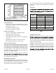
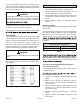
Refrigeration Charge Adjustment
Liquid Line Diameter Oz. Per Linear Foot
3/8” 0.6
Table 2.
350-450 CFM per ton (12,000 Btuh) through a wet coil.
Refer to indoor unit instructions for methods of determining
Cooling Cycle Charge Adjustment Procedure
Units with Indoor Pistons
Units installed with indoor pistons require charging with the
superheat method.
within ± 20 % of its rated CFM.
1. Operate unit a minimum of 10 minutes before checking
charge.
2. Measure suction pressure by attaching a gage to
suction valve service port. Determine saturation temp
from T/P chart.
3. Measure suction temperature by attaching an accurate
thermistor type or electronic thermometer to suction
line at service valve.
4. Calculate superheat (measured temp. - saturation
temp.).
5. Measure outdoor air dry-bulb temperature with
thermometer.
Remove access panel to gain access to unit wiring. Extend
wires from disconnect through power wiring hole provided
and into unit control box. Flexible conduit is required for the
swing out control box feature.
The unit cabinet must have an uninterrupted or unbroken
ground. The ground must be installed in accordance
with all electrical codes. Failure to follow this warning
WARNING
Connect ground wire to ground connection in control box
for safety. Connect power wiring to contactor.
High voltage power connections to 3-phase models is made
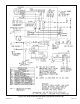
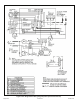
Contol Wiring
The control voltage is 24 VAC. NEC Class I insulated 18
AWG is required for control wiring. For lengths longer than
150 feet, contact your local distributor for technical service.
Ensure the room thermostat is properly installed per
instructions shipped with room thermostat. Generally the
thermostat should not be exposed to sunlight, drafts or
vibration and should not be mounted on exterior walls.
Low voltage wiring must be separated from high voltage
wiring.
WARNING
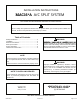
Low voltage connections should be in accordance to the
wiring diagram.
Figure 2. Typical Low Voltage Connection