
Instructions / Assembly

5 VERTICAL DOWNFLOW
IMPORTANT NOTE
4 VERTICAL UPFLOW
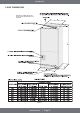
INDOOR UNIT
mrcool.com | Page 6
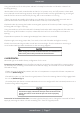
1) Vertical Upflow configuration is the factory set on all models (see Fig 1)
2) If a side return air opening is required, field fabricate a return air plenum with an opening large
enough to supply unit and strong enough to support unit weight.
3) If return air is to be ducted, install duct flush with floor. Use fireproof resilient gasket 1/8 in. to 1/4
in. thick between the ducts, unit, and floor. Set unit on the floor over the opening.
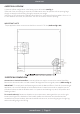
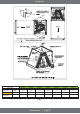
Conversion to Vertical Downflow: A vertical upflow unit may be converted to vertical downflow.
Remove the door and indoor coil and reinstall 180 degrees from its original position (Refer to Fig. 3).
IMPORTANT: To comply with certification agencies and the National Electric Code for horizontal right
application, the circuit breaker(s) on field-installed electric heater kits must be re-installed, per the
procedure below, so that the breaker switch ”on” position and marking is up and, ”off” position and
marking is down.
To rotate breaker(s): Rotate one breaker set (circuit) at a time, starting with the one on the right.
Loosen both lugs on the load side of the breaker (make sure that wires are identified and are
reinstalled into proper breaker). Wires are bundled with wire ties, one bundle going to the right lug
and one bundle going to the left lug.
Torque applied to drain connections should not exceed 15 ft. lbs. (Refer to Fig.1 & 2).