
Instructions / Assembly

It is important that proper electrical power is available for connection to the unit model being installed.
Please refer to the unit nameplate, wiring diagram, and electrical data in the installation instructions.
• If required, install a branch circuit disconnect of adequate size, located within sight of, and readily
accessible to the unit.
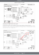
• IMPORTANT: After the Electric Heater is installed, units may be equipped with one, two, or three 30/60
amp. circuit breakers. These breaker(s) protect the internal wiring in the event of a short circuit and also
serve as a disconnect. Circuit breakers installed within the unit do not provide overcurrent protection of
the supply wiring and therefore may be sized larger than the branch circuit protection.
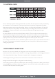
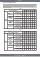
• Supply circuit power wiring must be 167°F (75°C) minimum copper conductors only. Refer to the
Electrical Data In this section for ampacity, wire size, and circuit protector requirement. Supply circuit
protective devices may be either fuses or “HACR” type circuit breakers.
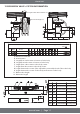
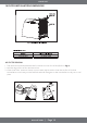
• Power wiring may be connected to either the right side, left side, or top. Concentric knockouts are
provided for connection of power wiring to unit.
• Power wiring is connected to the power terminal block in unit electric cabinet.
INDOOR UNIT
mrcool.com | Page 9
IMPORTANT: Class 2 low voltage control wiring should not be run in conduit with main power wiring and
must be separated from power wiring, unless class 1 wire of proper voltage rating is used.
• Low voltage control wiring should be 18 Awg. color-coded. For lengths longer than 100 ft., 16 Awg. wire
should be used.
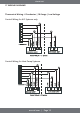
• See wiring diagrams attached to indoor and outdoor sections to be connected.
• Make sure, after installation, separation of control wiring and power wiring has been maintained.
The unit must be properly and permanently grounded. Failure to
do so can result In electrical shock causing personal injury or
death.
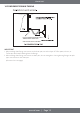
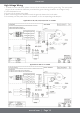
• Grounding may be accomplished by grounding metal conduit when installed in accordance with
electrical codes to the unit cabinet.
• Grounding may also be accomplished by attaching ground wire(s) to ground lug(s) provided in the unit
wiring compartment.
• Ground lug(s) are located close to wire entrance on left side of the unit (upflow). Lug(s) may be moved
to marked locations near wire entrance on right side of the unit (upflow). If alternate location is more
convenient.
• Use of multiple supply circuits require grounding of each circuit to lug(s) provided in unit.
8 POWER WIRING
9 CONTROL WIRING
10 GROUNDING
7 ELECTRICAL WIRING
Field wiring must comply with the National Electric Code and any applicable local ordinance.
Disconnect all power to unit before installing or servicing. More
than one disconnect switch may be required to de-energize the
equipment. Hazardous voltage can cause severe personal injury
or death.