
Install Manual


10.1 Main system Power
Size all wire i n accordance to l ocal electrical code. Main power will l and on top of the contactor,
labeled “L1 and L2”. A green ground l ug will also be provided for the ground wire.
10.2 Pump outputs
A terminal strip will be provided for each pump or water valve output that applies. Each will be
labeled as needed.
10.2.1 Motorized water valve (Open loop)
A 24 Vac terminal strip l abeled “ WATER VALVE” will be provided i nside the control panel. This i s a 3
wire connection i ncluding common, power open and power close. Two wire valves can also be
utilized.
10.2.2 Loop Pump (closed loop systems)
A 230V fused terminal strip l abeled “ CLOSED LOOP PUMP ” i s provided i nside the control panel for
the field -i nstalled ground l oop pump. When the fuse i s tripped, an ORANGE LED will l ight up on the
terminal.
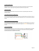
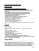
10.3 Thermostat Wiring
The thermostat will wire directly to the removable terminal block on the Dallas Board and i s labeled
using common thermostat l ettering. (See i mage below for sample thermostat wiring. Consult
thermostat manual for installation instructions ).
Page 20