
Install Manual
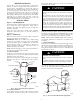
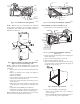
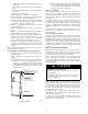
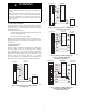

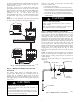


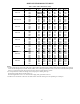
Table Of Contents

6
R
G
C
L
E
O
C147C963
Y
THERMOSTAT
R
R
C
O
Y
G
C
W
2
W
2
W
2
W
3
E
FAN COIL
(CONTROL)
EMERGENCY HEAT RELAY
HEAT PUMP
(CONTROL)
ODTS1
ODTS2
RED
GRY
BRN
WHT
BLU
VIO
A94062
Fig. 13 -- Wiring Layout Heat Pump Unit (Cooling and
2--Stage Heat with 2 Outdoor Thermostats)
R
E
W2
R
C
THERMOSTAT
FAN COIL
(CONTROL)
HEAT PUMP
(CONTROL)
G
C
W2
E
L
G
C
R
O
Y
ODTS
O
Y
W3
W2
A03088
Fig. 14 -- Wiring Layout Heat Pump Unit
(Cooling and 2--Stage Heat for Manufactured Housing)
Refer to outdoor unit wiring instructions for any additional wiring
procedure recommendations.
Transformer Information
Transformer is factory--wired for 230v operation. For 208v
applications, disconnect the black wire from the 230v terminal on
transformer and connect it to the 208v terminal. (See Fig. 15.)
230
C
208
BRN
RED
YEL
BLK
SECONDARY
PRIMAR
Y
A05182
Fig. 15 -- Transformer Connections
Heater Staging
PROPERTY DAMAGE HAZARD
Failure to follow this caution may result in product or
property damage.
If W2, W3, and E on any 3 stage heater (18, 20, 24, or
30kW) are individually connected as with outdoor
thermostats or any other situation, emergency heat relay must
be used. This relay is in kit Part No. KHOT0201SEC and is
normally used with kit Part No. KHAOT0301FST for 2
outdoor thermostat systems.
CAUTION
!
The controls are factory circuited for single--stage operation. For
2--stage operation, use outdoor thermostat kit Part No.
KHAOT0301FST, and for 3--stage use both kits Part No.
KHAOT0201SEC and KHAOT0301FST.
When 2 stages are desired, cut W3 at the W2 wire nut, strip and
reconnect per the thermostat kit instruction. (See Fig. 13.) When 3
stages are desired, cut the W2 wire nut off and discard. Strip W2,
W3, and E and reconnect per thermostat kit instructions. (See Fig.
13.)
NOTE: When 3 stages are used or anytime the E terminal is not
tied to W2, the emergency heat relay, part of outdoor kit Part No.
KHAOT0201SEC must be used.
C. Manufactured Housing
In manufactured housing applications, the Code of Federal
Regulations, Title 24, Chapter XX, Part 3280.714 requires that
supplemental electric heat be locked out at outdoor temperatures
above 40_F(4_C), except for a heat pump defrost cycle. Refer to
Fig. 14 for typical low voltage wiring with outdoor thermostat.
D. Ground Connections
ELECTRICAL SHOCK HAZARD
Failure to follow this warning could result in personal injury
or death.
According to NEC, ANSI/NFPA 70, and local codes, the
cabinet must have an uninterrupted or unbroken ground to
minimize personal injury if an electrical fault should occur.
The ground may consist of electrical wire or metal conduit
when installed in accordance with existing electrical codes. If
conduit connection uses reducing washers, a separate ground
wire must be used.
!
WARNING
NOTE: Use UL--listed conduit and conduit connector for
connecting supply wire(s) to unit to obtain proper grounding.
Grounding may also be accomplished by using grounding lugs
provided in control box.
E. Minimum CFM and Motor Speed Selection
The fan speed selection is done at the motor connector. Units with
or without electric heaters require a minimum CFM. Refer to the
unit wiring label to ensure that the fan speed selected is not lower
than the minimum fan speed indicated.
Tap 1 Low 90 sec off delay
Tap 2 Medium 90 sec off delay
Tap 3 High 90 sec off delay
Tap 4 Electric heat † 0 sec off delay
Tap 5 Max ‡ 0 sec off delay
† electric heat airflow is same CFM as Tap 3, except 0 sec off delay
‡ high static applications, see airflow tables for max airflow