
Install Manual
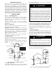
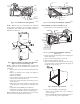
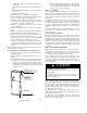
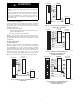

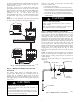


Table Of Contents

5
ELECTRICAL SHOCK HAZARD
Failure to follow this warning could result in personal injury
or death.
Field wires on the line side of the disconnect found in the fan
coil unit remain live, even when the pull--out is removed.
Service and maintenance to incoming wiring cannot be
performed until the main disconnect switch (remote to the
unit) is turned off.
!
WARNING
A. Line Voltage Connections
If unit will contain accessory electric heater, remove and discard
power plug from fan coil and connect male plug from heater to
female plug from unit wiring harness. (See Electric Heater
Installation Instructions.)
For units without electric heater:
1. Connect 208/230v power leads from field disconnect to yel-
low and black stripped leads.
2. Connect ground wire to unit ground lug.
NOTE: Units installed without electric heat should have a
field--supplied sheet metal block--off plate covering the heater
opening. This will reduce air leakage and formation of exterior
condensation.
B. 24--v Control System
Connection To Unit
Wire low voltage in accordance with wiring label on the blower.
(See Fig. 9 through 14.) Use no. 18 AWG color--coded, insulated
(35_C minimum) wire to make the low--voltage connections
between the thermostat, the unit, and the outdoor equipment. If the
thermostat is located more than 100--ft (30 m) from the unit (as
measured along the low--voltage wire), use no. 16 AWG
color--coded, insulated (35_C minimum) wire. All wiring must be
NEC Class 1 and must be separated from incoming power leads.
R
G
W
Y
THERMOSTAT
RED
GRY
WHT
BLU
VIO
BRN
WHT
R
G
W
2
W
3
E
C
FAN COIL
(CONTROL)
C
Y
AIR COND.
A94058
Fig. 9 -- Wiring Layout Air Conditioning Unit
(Cooling Only)
R
G
W
Y
THERMOSTAT
R
G
W
2
W
3
E
C
FAN COIL
(CONTROL)
C
Y
AIR COND.
RED
GRY
WHT
WHT
BLU
VIO
BRN
A94059
Fig. 10 -- Wiring Layout Air Conditioning Unit
(Cooling and 1--Stage Heat)
R
G
C
E
L
O
Y
THERMOSTAT
R
R
C
O
Y
G
C
W
2
W
2
W
2
W
3
E
FAN COIL
(CONTROL)
HEAT PUMP
(CONTROL)
RED
GRY
BRN
WHT
BLU
VIO
A94060
Fig. 11 -- Wiring Layout Heat Pump Unit
(Cooling and 2--Stage Heat with
No Outdoor Thermostat)
R
G
C
E
L
O
Y
THERMOSTAT
R
R
C
O
Y
G
C
W
2
W
2
W
2
W
3
E
ODTS
FAN COIL
(CONTROL)
HEAT PUMP
(CONTROL)
RED
GRY
BRN
WHT
VIO
BLU
A94061
Fig. 12 -- Wiring Layout Heat Pump Unit
(Cooling and 2--Stage Heat with
1 Outdoor Thermostat)