HEATER PACKAGES This unit may or may not be equipped with an electric heater package. For units not equipped with factory--installed heat, a factory--approved, field--installed, UL listed heater package is available from your equipment supplier. See unit rating plate for a list of factory--approved heaters. Heaters that are not factory approved could cause damage which would not be covered under the equipment warranty.
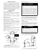
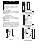
COIL MOUNTING SCREW A BLOWER ASSEMBLY COIL BRACKET FA CT OR Y SHIPPED HORIZONTAL LEFT APPLICATION COI L SUPPORT RAIL B C COIL SUPPORT RAIL DRAIN PA N SUPPORT BRACKET COIL BRACKET SLOPE COIL SKI HORIZONTAL DRAIN PAN PRIMARY DRAIN HORIZONTAL LEFT AIR SEAL ASSEMBLY DRAINPAN SECONDARY DRAIN HORIZONTAL LEFT REFRIGERANT CONNECTIONS SECONDARY DRAIN REFRIGERANT CONNECTIONS A03001 A00072 Fig. 5 -- Conversion for Horizontal Right Applications Fig.
c. Remove filter plate (A) and install air splitter (B) in place of filter plate. d. Install filter plate (A) as shown in horizontal right application. e. Remove condensate troughs (C) and install on opposite tube sheets. f. Install hose onto plastic spout. 7. Install horizontal pan on right side of coil assembly. 8. Slide coil assembly into casing. Be sure coil bracket on each corner of vertical pan engages coil support rails. 9.
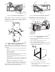
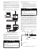
WARNING ! FAN COIL (CONTROL) THERMOSTAT RED R ELECTRICAL SHOCK HAZARD Failure to follow this warning could result in personal injury or death. W R GRY G G WHT W2 WHT BLU Field wires on the line side of the disconnect found in the fan coil unit remain live, even when the pull--out is removed. Service and maintenance to incoming wiring cannot be performed until the main disconnect switch (remote to the unit) is turned off. W3 VIO E BRN AIR COND. C C RED R GRY G W A94059 Fig.
FAN COIL (CONTROL) THERMOSTAT RED R R G C BRN C W2 WHT W 2 C Failure to follow this caution may result in product or property damage. W2 If W2, W3, and E on any 3 stage heater (18, 20, 24, or 30kW) are individually connected as with outdoor thermostats or any other situation, emergency heat relay must be used. This relay is in kit Part No. KHOT0201SEC and is normally used with kit Part No. KHAOT0301FST for 2 outdoor thermostat systems.
To change motor speeds disconnect the BLUE fan lead from motor connector terminal #2 (factory default position) and move to desired speed-tap; 1, 2, 3, or 5. Speed-taps 1, 2, and 3 have a 90 second blower off time delay pre-programmed into the motor. Speed-tap 4 is used for electric heat only (with 0 second blower time delay) and the WHITE wire should remain on tap 4. Speed-tap 5 is used for high static applications, but has a 0 second blower time delay pre-programmed into the motor.
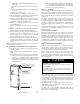
! CAUTION PRODUCT OPERATION HAZARD Failure to follow this caution may result in improper product operation. FILTER ACCESS PANEL If using a TXV in conjunction with a single--phase reciprocating compressor, a compressor start capacitor and relay are required. Consult outdoor unit pre--sale literature for start assist kit part number. SECONDARY DRAIN WITH APPROPRIATE TRAP REQUIRED (USE FACTORY KIT OR FIELD-SUPPLIED TRAP) PRIMARY TRAP REQUIRED (USE FACTORY KIT OR FIELD-SUPPLIED TRAP OF SUFFICIENT DEPTH.
Step 9 — Sequence of Operation A. Continuous Fan Thermostat closes R to G. G energizes fan relay on PCB which completes circuit to indoor blower motor. When G is de--energized, there is a 90--sec delay before relay opens. B. Cooling Mode Thermostat energizes R to G, R to Y, and R to O (heat pump only). G energizes fan relay on PCB which completes circuit to indoor blower motor. When G is de--energized, there is a 90--sec delay before fan relay opens. C.
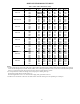
AIRFLOW PERFORMANCE TABLES Table 1 – FB4C Airflow Performance (CFM) MODEL & SIZE FB4C 018 FB4C 024 / 025 FB4C 030 FB4C 036 FB4C 042 FB4C 048 FB4C 060 FB4C 061 BLOWER SPEED Tap 5 Tap 4 Tap 3 Tap 2 Tap 1 Tap 5 Tap 4 Tap 3 Tap 2 Tap 1 Tap 5 Tap 4 Tap 3 Tap 2 Tap 1 Tap 5 Tap 4 Tap 3 Tap 2 Tap 1 Tap 5 Tap 4 Tap 3 Tap 2 Tap 1 Tap 5 Tap 4 Tap 3 Tap 2 Tap 1 Tap 5 Tap 4 Tap 3 Tap 2 Tap 1 Tap 5 Tap 4 Tap 3 Tap 2 Tap 1 0.
AIRFLOW PERFORMANCE TABLES (cont.) Table 2 – FB4C Air Delivery Performance Correction Component Pressure Drop (in. wc) at Indicated Airflow (Dry to Wet Coil) UNIT SIZE 500 018 0.034 600 0.049 700 0.063 800 900 1000 1100 -- -- ---- CFM 1200 1300 1500 1600 1700 1800 1900 2000 ------ ------- ------- -------- 024 0.034 0.049 0.063 0.076 0.089 025 0.015 0.026 0.038 0.049 0.059 030 ------- ------- ------- 0.049 0.059 0.070 0.080 ----- ------ ------ 0.070 0.080 0.
I M