
Install Manual

Page 16
mrcool.com
•
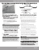
CAUTION
•
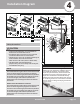
To prevent wall damage, use a stud finder to
locate studs to mount the units to.
A minimum pipe run of 9.8 ft (3 m) is required
to minimize vibration & excessive noise.
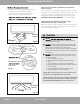
Two of the A, B, and C air circulation pathways of
of the outdoor unit must be free from
obstructions at all times (Refer to illustration).
This illustration is for demonstration
purposes only. The actual shape and size of your
air condtioner may vary.
•
•
Safety Precautions
1
2
3
4
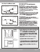
1
Installation plate
Mounting screw
ST3.9
× 25-C-H
Clip anchor
(1)
Remote
controller
holder
4 3
2
Air-break Switch
Drainage
Pipe
Air-break
Switch
Outdoor Unit
Power Cable
4
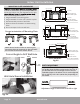
Installation Diagram
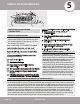
27K BTU 3 Zone DIY Multi-Zone Condenser
The combined linear length of all line-sets shall not exceed
197 ft. The linear length of any single line-set shall not
exceed 75 ft. The lateral length (vertical distance) between
the outdoor unit and any indoor unit shall not exceed 49
ft. The lateral length (vertical distance) between the
lowest indoor unit and the highest indoor unit shall not
exceed 33 ft.
36K BTU 4 Zone DIY Multi-Zone Condenser
The combined linear length of all line-sets shall not exceed
262 ft. The linear length of any single line-set shall not
exceed 75 ft. The lateral length (vertical distance) between
the outdoor unit and any indoor unit shall not exceed 49
ft. The lateral length (vertical distance) between the
lowest indoor unit and the highest indoor unit shall not
exceed 33 ft.
NOTE:
One-Two
One-Three
One-Four
More than
24 in
(60cm)
More than
24 in
(60cm)
More
than 12 in
(30 cm)
More than
79 in
(200 cm)
More than
12 in
(30 cm)
More than
4.7 in (12 cm)
More than 6 in
(15 cm)
More than
4.7 in (12 cm)
More than
4.7 in (12 cm)
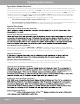
Additional Line Sets & Coupler Kit
If you find the default line set lengths are not
sufficient for your application, additional line sets
are available for purchase. You will also need a
coupler kit (pictured below), which will allow two
standard line sets to be connected together. The
coupler kit is installed and checked for leaks by
following the same steps described in this manual
for connecting the line set to the indoor air handler
(Refer to Section 7: Refrigerant Piping Connections
for these steps).