
Installation Guide


Page 17
Step 6: Connect indoor power wire
The cable enables communication between
the indoor and outdoor units. You must first
choose the right cable size before preparing it for
connection.
Cable Types
Indoor Power Cable (if applicable):
H05VV-F or H05V2V2-F
Outdoor Power Cable: H07RN-F
Signal Cable: H07RN-F
Minimum Cross-Sectional Area of
Power and Signal Cables
Other Regions
Rated Current of
NominalCro ss Sectional
-
Appliance (A)
2
Area (mm )
> 3 and 6 0.75
> 6 and 10
> 10 and 16 1.5
1.0
> 16 and 25 2.5
> 25 and 32 4
> 32 and 40 6
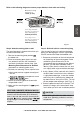
CHOOSE THE RIGHT CABLE SIZE
The size of the power supply cable, signal
cable, fuse, and switch needed is determined
by the maximum current of the unit. The
maximum current is indicated on the nameplate
located on the side panel of the unit. Refer to
this nameplate to choose the right cable, fuse,
or switch.
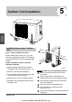
Indoor Unit
Installation
TAKE NOTE OF FUSE SPECIFICATIONS
The air conditioner s circuit board (PCB) is
designed with a fuse to provide overcurrent
protection. The specifcations of the fuse
are printed on the circuit board, such as:
T3.15A/250VAC, T5A/250VAC, etc.
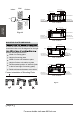
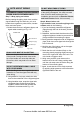
1. Prepare the cable for connection:
WARNING
IN ACCORDANCE WITH THE WIRING
DIAGRAM LOCATED ON THE INSIDE OF THE
INDOOR UNIT S WIRE COVER.
,
ALL WIRING MUST PERFORMED STRICTL
,
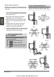
Connector
Power
supply
Indoor unit
Y/G
Outdoor unit
L N1
3
2
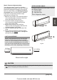
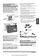
Hold the indoor plug connector and insert the
mating plug connector located on the outdoor
unit until it fixed with a clicking sound. The Y/G
wire should be connected individually. Secure
the cable onto the control board with the cord
clamp. See Fig.4.9 for example:
Fig. 4.9
NOTE ABOUT WIRING
THE WIRING CONNECTION PROCESS MAY
DIFFER SLIGHTLY BETWEEN UNITS
For more details visit www.MrCool.com
Appliance
Amps (A)
AWG
20 12
25
10
35
8
12K & 18K
24K
36K
Model Series
North America