Please read this manual carefully before installation and keep it for future reference. Installation Manual DIY Series Please keep this manual where the operator can easily find it. Inside you will find helpful hints on how to use and maintain your unit properly. For more details visit www.MrCool.
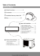
Table of Contents Installation Manual 0 Safety Precautions.................................4 1 Accessories .............................................. 6 2 Installation Summary- Indoor Unit .......8 3 Parts ...............................................10 4 Indoor Unit Installation .............11 1. Select installation location .....................11 2. Attach mounting plate to wall .............. 12 3. Drill wall hole for connective piping ......12 4. Prepare refrigerant piping .....................
6 Refrigerant Piping Connection.............23 Connecting the refrigerant pipe to outdoor unit .........25 MC MC 7 Electrical and Gas Leak Checks.............25 8 Test Run ................................................26 9 EU Disposal Guidelines ..............28 For more details visit www.MrCool.
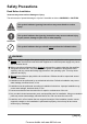
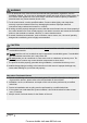
Safety Precautions Read Before Installation Incorrect may cause serious damage or injury. The seriousness of potential damage or injuries is classifed as either a WARNING or CAUTION. This symbol indicates ignoring instructions may cause death or serious injury. WARNING This symbol indicates that ignoring instructions may cause moderate injury to your person, damage to your unit, or other property. CAUTION This symbol indicates that you should never perform the indicated action.
WARNING 6. For all electrical work, follow all local and national wiring standards, regulations, and the Installation Manual. You must use an independent circuit and single outlet to supply power. Do not connect other appliances to the same outlet. Insufficient electrical capacity or defects in electrical work may cause electrical shock or fire. 7. For all electrical work, use the specified cables. Connect cables tightly, and clamp them securely to prevent external forces from damaging the terminal.
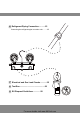
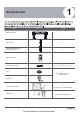
1 Accessories Name Shape Quantity Mounting plate 1 Clip anchor 5 Mounting plate fixing screw ST3.9 X 25 5 Remote control 1 Air freshening filter 1 (used to install on the back of air filter) Seal 1 (for cooling & heating models only) Drain joint Smart Controller Kit 1 (w/ Manual in Controller Box) 1 (Sealant for Wall Sleeve) Neoprene Page 6 For more details visit www.MrCool.
SPLIT-TYPE ROOM AIR CONDITIONER Owner s Manual User's Manual CS78421-548-754 1 IMPORTANT NOTE: Read this manual carefully before installing or operating your new air conditioning unit. Make sure to save this manual for future reference. SPLIT-TYPE ROOM AIR CONDITIONER Installation Manual 1 Installation Manual IMPORTANT NOTE: Read this manual carefully before installing or operating your new air conditioning unit. Make sure to save this manual for future reference.
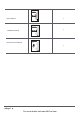
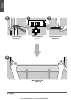
1 2 2 Minimum Ceiling Clearance is 15cm (5.9in) >12cm (4.75in) >12cm (4.75in) For Ceilings Greater Than 9 Foot Suggested Floor Clearance is 230cm(90.55in) For Ceilings Less Than 9 Foot Suggested Floor Clearance is 200cm(78.55in) Select Installation Location (Page 11) 3 Determine Wall Hole Position (Page 12) 4 Attach Mounting Plate (Page 12) Drill Wall Hole (Page 12) Page 8 For more details visit www.MrCool.
Installation Overview 5 6 7 L Connect Piping (Page 25 ) N S Connect Wiring (Page 17) 8 STEP 8 Mount Indoor Unit (Page 18) Page 9 For more details visit www.MrCool.
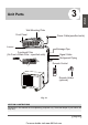
Installation Overview 3 Unit Parts Wall Mounting Plate Front Panel Power Cable(specified units) Louver Drainage Pipe Functional Filter (On Front of Main Filter - specified units) Signal Cable Refrigerant Piping Remote Control Remote Holder (optional) Fig. 3.1 NOTE ON ILLUSTRATIONS Illustrations in this manual are for explanatory purposes only. The actual shape of your indoor unit may vary. Page 10 For more details visit www.MrCool.
4 Indoor Unit Installation Indoor Unit Installation Installation Instructions - Indoor Unit PRIOR TO INSTALLATION Before installing the indoor unit, refer to the label on the product box to make sure that the model number of the indoor unit matches the model number of the outdoor unit. Step 1: Select installation location Before installing the indoor unit, you must choose an appropriate location. The following standards will help you choose an appropriate location.
Refer to the following diagram to ensure proper distance from walls and ceiling: Minimum Ceiling Clearance is 15cm (5.9in) >12cm (4.75in) >12cm (4.75in) Indoor Unit Installation For Ceilings Greater Than 9 Foot Suggested Floor Clearance is 230cm(90.55in) For Ceilings Less Than 9 Foot Suggested Floor Clearance is 200cm(78.55in) Fig. 4.1 Step 2: Attach mounting plate to wall Step 3: Drill wall hole for connective piping The mounting plate is the device on which you will mount the indoor unit.
Wall Indoor Outdoor 426mm(16.8in) 43mm (1.7in) Indoor unit outline Left rear wall hole 90mm (3.5in) 43mm (1.7in) 297mm (11.7in) 802mm (31.6in) Right rear wall hole 90mm (3.5in) Series 12K Models Indoor Unit Installation 517.4mm(20.37in) 144mm (5.65in) Left rear wall hole 90mm (3.5in) Indoor unit outline 34mm (1.35in) 40mm (1.55in) Fig. 4.2 57mm (2.25in) 319mm (12.55in) 138mm (5.45in) 58mm (2.3in) 5-7mm (0.2-0.3in) 128mm (5.05in) 43mm (1.7in) 232mm (9.15in) 192mm (7.
Step 4: Prepare refrigerant piping The refrigerant piping is inside an insulating sleeve attached to the back of the unit. You must prepare the piping before passing it through the hole in the wall. Refer to the Refrigerant Piping Connection section of this manual for detailed instructions on pipe faring and fare torque requirements, technique, etc. NOTE ON PIPING ANGLE Refrigerant piping can exit the indoor unit from two different angles: Left-hand side Right-hand side Refer to Fig. 4.4 for details.
Step 5: Connect drain hose PLUG THE UNUSED DRAIN HOLE By default, the drain hose is attached to the left, hand side of unit (when you re facing the back of the unit). To prevent leaks you must plug the excess space in the drain hole with the rubber plug. . 1. To ensure proper drainage, attach the drain hose on the same side that your refrigerant piping exits the unit. CORRECT 2. Attach drain hose extension (purchased separately) to the end of drain hose.
BEFORE PERFORMING ELECTRICAL WORK, READ THESE REGULATIONS 1. All wiring must comply with local and national electrical codes, and must be installed by a licensed electrician. 2. All electrical connections must be made according to the Electrical Connection Diagram located on the panels of the indoor and outdoor units. 3. If there is a serious safety issue with the power supply, stop work immediately.
Step 6: Connect indoor power wire TAKE NOTE OF FUSE SPECIFICATIONS The cable enables communication between the indoor and outdoor units. You must first choose the right cable size before preparing it for connection. The air conditioner s circuit board (PCB) is designed with a fuse to provide overcurrent protection. The specifcations of the fuse are printed on the circuit board, such as: T3.15A/250VAC, T5A/250VAC, etc.
NOTE ABOUT WIRING THE WIRING CONNECTION PROCESS MAY DIFFER SLIGHTLY BETWEEN UNITS Step 7: Wrap piping and cables Before passing the piping, drain hose, and the signal cable through the wall hole, you must bundle them together to protect them, insulate them, and save space. Indoor Unit When wrapping the bundle, keep the ends of the piping unwrapped. You need to access them to test for leaks at the end of the installation process (refer to Electrical Checks and Leak Checks section of this manual).
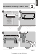
5 Outdoor Unit Installation 30cm on le (12in) ft 60cm (24in) above Outdoor Unit Installation Installation Instructions- Outdoor Unit in ) all (1 2 k w c m a c 30 m b fro Step 1: Select installation location Before installing the outdoor unit, you must choose an appropriate location. The following standards will help you choose an appropriate location.
SPECIAL CONSIDERATIONS FOR EXTREME WEATHER If the drain joint comes with a rubber seal (see Fig. 4.4 - A), do the following: If the unit is exposed to heavy wind: 1. Fit the rubber seal on the end of the drain joint that will connect to the outdoor unit. Install unit so that air outlet fan is at a 9 o 0 angle to the direction of the wind. If needed, build a barrier in front of the unit to protect it from extremely heavy winds. 2. Insert the drain joint into the hole in the base pan of the unit.
Step 3: Anchor outdoor unit The outdoor unit can be anchored to the ground or to a wall-mounted bracket. UNIT MOUNTING DIMENSIONS H sizes and the distance between their mounting feet. Prepare the installation base of the unit according to the dimensions below. W A Air Inlet Air Inlet D Outdoor Unit Installation B Fig. 4.5 Air Outlet Outdoor Unit Dimensions (inches) Width (W) x Height (H) x Depth (D) Mounting Dimensions (inches) Width (A) Depth (B) DIY-12-HP-C-115A 30.7 x 21.25 x 9.
If you install the unit on a wall-mounted bracket, do the following: CAUTION Before installing a wall-mounted unit, make sure that the wall is made of solid brick, concrete, or of similarly strong material. The wall must be able to support at least four times the weight of the unit. 1. Mark the position of bracket holes based on dimensions in the Unit Mounting Dimensions chart. 2. Pre-drill the holes for the expansion bolts. 1.
6 Refrigerant Piping Connection Connecting the refrigerant pipe to outdoor unit CAUTION: For your safet, always wear goggles and work gloves when connecting the pipes. NOTE: To distinguish the connectors to be connected to the indoor unit and outdoor unit, the connectors of the refrigerant pipe has been labelled A , B , C and D . Ensure the marks on the connector are the , , same to the indoor s and outdoor s respectively during connection. 1.
Coupling size (last 2 part numbers) Pound-force foot(1bf-ft) Newton meter(N-m) Kilogram-force meter(kgf-m) -06(9.5mm dash size) 18 - 20 24.4 - 27.1 2.4 - 2.7 -08(12.7mm dash size) 30 - 35 40.6 - 47.4 4.1 - 4.8 -12(19.1mm dash size) 45 - 50 61.0 - 67.7 6.2 - 6.9 -16(25.4mm dash size) 60 - 65 81.3 - 88.1 8.2 - 8.9 After completing steps 1- 4, check that all the connections are sealed correctly using leak detection spray or soap suds.
Electrical and Gas Leak Checks Electrical Safety Checks After installation, confirm that all electrical wiring is installed in accordance with local and national regulations, and according to the Installation Manual. BEFORE TEST RUN Check Grounding Work 7 WARNING - RISK OF ELECTRIC SHOCK ALL WIRING MUST COMPLY WITH LOCAL AND NATIONAL ELECTRICAL CODES, AND MUST BE INSTALLED BY A LICENSED ELECTRICIAN.
8 Test Run List of Checks to Perform Before Test Run Only perform test run after you have completed the following steps: Electrical Safety Checks - Confirm that , the unit s electrical system is safe and operating properly. Gas Leak Checks - Check all fare nut connections and confirm that the system is not leaking. Confirm that gas and liquid (high and low pressure) valves are fully open. Test Run Instructions You should perform the Test Run for at least 30 minutes. 1. Connect power to the unit. 2.
DOUBLE-CHECK PIPE CONNECTIONS During operation, the pressure of the refrigerant circuit will increase. This may reveal leaks that were not present during your initial leak check. Take time during the Test Run to double-check that all refrigerant pipe connection points do not have leaks. Refer to Gas Leak Check section for instructions. 5. After the Test Run is successfully complete, and you confirm that all checks points in List of Checks to Perform have PASSED, do the following: Manual control button a.
EU Disposal Guidelines 9 This appliance contains refrigerant and other potentially hazardous materials. When disposing of this appliance, the law requires special collection and treatment. Do not dispose of this product as household waste or unsorted municipal waste. When disposing of this appliance you have the following options: Dispose of the appliance at a designated municipal electronic waste collection facility. When buying a new appliance, the retailer will receive the old appliance free of charge.
DIY Series The design and specifications are subject to change without prior notice. Consult with the sales agency or manufacturer for details. For more details visit www.MrCool.