
Install Manual
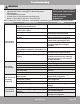

mrcool.com
Index:
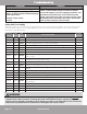
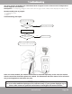
1. Indoor or Outdoor DC Fan Motor(control chip is in fan motor)
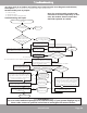
Power on and when the unit is in standby, measure the voltage of pin1-pin3, pin4-pin3 in the fan motor connector.
If the value of the voltage is not in the range shown in the table below, the PCB needs to be replaced.
•
DC motor voltage input and output (voltage: 220-240V~):
No. Color Signal Voltage
1 Red Vs/Vm 280V~380V
2 --- --- ---
3 Black GND 0V
4 White Vcc 14-17.5V
5 Yellow Vsp 0~5.6V
6 Blue FG 14-17.5V
•
DC motor voltage input and output (voltage: 115V~):
No. Color Signal Voltage
1 Red Vs/Vm 140V~190V
2 --- --- ---
3 Black GND 0V
4 White Vcc 14-17.5V
5 Yellow Vsp 0~5.6V
6 Blue FG 14-17.5V
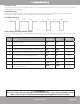
2. Outdoor DC Fan Motor (control chip is in outdoor PCB)
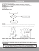
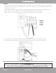
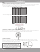
Release the UVW connector. Measure the resistance of U-V, U-W, V-W. If the resistance of each is not equal to one
another, the fan motor needs to be replaced. If they are equal, the PCB needs to be replaced.
Page 47
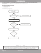
3. Indoor AC Fan Motor
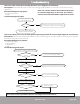
Power on the unit and run it in fan mode with the fan speed setting set to high. After running for 15 seconds,
measure the voltage of pin 1 and pin 2. If the value of the voltage is less than 100V (208~240V power supply) or
50V (115V power supply), the PCB needs to be replaced.
****Disclaimer****
The error codes and descriptions are for
reference only. If your system displays any
of these codes contact a qualified technician
to investigate the matter further.