
Install Manual

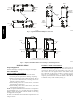
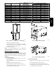
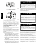
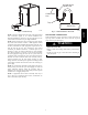

Table Of Contents

4
Unbend tab as
shown, 4 places.
A13064
Fig. 6 -- Horizontal Left Installation
Self-Tapping Screws
A13066
Fig. 7 -- Horizontal Left Installation
CONNECT REFRIGERANT PIPING
Use accessory tubing package or field--supplied tubing of
refrigerant grade, see Product Data information for ordering.
Suction tube must be insulated. Do not use damaged, dirty, or
contaminated tubing because it may plug refrigerant flow--control
device. ALWAYS evacuate the coil and field--supplied tubing
before opening outdoor unit service valves.
CONNECT REFRIGERANT, LIQUID, AND
SUCTION LINES
For matched and mismatched systems, use line sizes recommended
in outdoor unit Installation Instructions.
The coil can be connected to outdoor units using accessory tubing
packages or field--supplied tubing of refrigerant grade. Always
evacuate tubing and reclaim refrigerant when making connections
or flaring tubing. Leak check connections before insulating entire
suction line.
See Table 1 for coil connection tube size.
1. Remove cabinet door. Remove tubing plate with rubber
grommets and slide plate with grommets onto the
refrigerant lines (field line--set), away from braze joints.
2. Remove rubber plugs from coil stubs using a pulling and
twisting motion. Hold coil stubs steady to avoid bending or
distorting.
3. Wrap TXV and nearby tubing with a heat--sinking material
such as a wet cloth.
4. Fit refrigerant lines into coil stubs. Wrap a heat sinking
material such as a wet cloth behind braze joints.
5. Braze using a Sil--Fos or Phos--copper alloy.
6. After brazing, allow joints to cool. Slide tubing plate with
rubber grommets over joints. Position tubing at center of
each grommet to ensure an air seal around the tube.
UNIT DAMAGE HAZARD
Failure to follow this caution may result in product damage.
To avoid valve damage to the refrigerant control device while
brazing, valves must be wrapped with a heat--sinking material
such as a wet cloth.
CAUTION
!
REFRIGERANT METERING DEVICE
The CAPMP coil has a factory--installed hard shut--off TXV
designed only for use with R--410A refrigerant. Use only with
outdoor units designed for R--410A.
NOTE: All TXV’S have preset superheat settings and are field
non--adjustable.
UNIT DAMAGE HAZARD
Failure to follow this caution may result in product damage.
DO NOT BURY MORE THAN 36” (914 mm) OF
REFRIGERANT TUBING IN GROUND. If any section of
tubing is buried, there must be a 6” (152 mm) vertical rise to the
valve connections on the outdoor unit. If more than the
recommended length is buried, refrigerant may migrate to cooler
buried section during extended periods of unit shutdown,
causing refrigerant slugging and possible compressor damage at
start--up.
CAUTION
!
CONDENSATE LINE CONNECTION
PROPERTY DAMAGE HAZARD
Failure to follow this caution may result in property damage.
When installing over a finished ceiling and/or living area,
install a field--fabricated secondary condensate pan under the
entire unit.
CAUTION
!
The coil is designed to dispose of accumulated water through
built--in condensate drain fittings. It is recommended that PVC
fittings be used on the condensate pan. Do not over--tighten. Finger
tighten plus 1--1/2 turns. Be sure to install plastic plug in unused
condensate drain fitting. Two 3/4”. female threaded pipe
connections are provided in each coil condensate pan.
A trap is not necessary on the condensate line. Consult local codes
for additional restrictions or precautions. If local codes require a
trap then the following guidelines are suggested to assure proper
drainage. Install a trap in condensate line of coil as close to the coil
as possible. Make trap at least 3“ (76 mm) deep and no higher than
the bottom of unit condensate drain opening (See Fig. 8). Pitch
condensate line 1” (25.4 mm) for every 10 ft. of length to an open
drain or sump. Make sure that the outlet of each trap is below its
connection to condensate pan to prevent condensate from
overflowing the drain pan. Prime all traps, test for leaks, and
insulate traps and lines if located above a living area.
CAPMP