
Install Manual

Page 23
mrcool.com
Outdoor Unit Installation
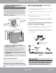
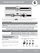
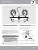
Fig. 5.6
ALL WIRING MUST PERFORMED STRICTLY IN
ACCORDANCE WITH THE WIRING DIAGRAM
LOCATED INSIDE THE OUTDOOR UNIT’S WIRE
COVER.
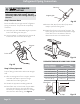
1.
Prepare the cable for connection:
USE THE RIGHT CABLE
BEFORE PERFORMING ANY ELECTRICAL
OR WIRING WORK, TURN OFF THE
MAINPOWER TO THE SYSTEM.
North America
2. Remove the electrical wiring cover from the unit by
loosening the 3 retaining screws. Refer to Fig. 5.6.
3. Remove the caps on the conduit panel.
4. Temporarily mount the conduit tubes (not
included) on the conduit panel.
5. Properly connect both the power supply and low
voltage lines to the corresponding terminals on
the terminal block.
6. Ground the unit in accordance with local codes.
7. Be sure to size each wire so that it allows for it to
be several inches longer than the required length
for wiring.
8. Use lock nuts to secure the conduit tubes.
9. Replace the wire cover and reinstall the 3 screws.
•
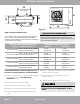
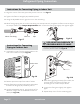
See table below for gauge requirements
Appliance
Amps(A)
AWG
15
15
20
25
24K
36K
Model
Series
Minimum Wire Gauge
for Power Cables
MCA MOP
15
20
25
35
14
12
10
12
G
Wire Cover
Terminal block
Conduit panel
Connecting cable
Power supply cord
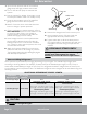
Please select the appropriate through-hole
according to the diameter of the wire.
Over 1.57 in.(40 mm)