
Installation Guide


Page 16mrcool.com
Indoor Unit Installation
Step 6: Connect signal cable
TAKE NOTE OF FUSE SPECIFICATIONS
The air conditioner’s circuit board (PCB) is
designed with a fuse to provide overcurrent
protection. The specifications of the fuse are
printed on the circuit board, such as:
T3.15A/250VAC, T5A/250VAC, etc.
CHOOSE THE APPROPRIATE CABLE SIZE
The size of the power supply cable, signal
cable, fuse, and switch needed is determined
by the maximum unit current. The maximum
unit current is indicated on the nameplate
located on the side panel of the unit. Refer
to this nameplate to choose the right cable,
fuse, or switch.
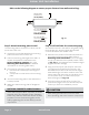
1. Prepare the cable for connection:
2. Open front panel of the indoor unit.
3. Using a screwdriver, open the wire box cover on
the right side of the unit. This will reveal the
terminal block.
4. Unscrew the cable clamp below the terminal
block and place it to the side.
5. Facing the back of the unit, remove the plastic
panel on the bottom left-hand side.
All wiring must be performed in
accordance with the wiring diagram
Fig. 4.7a shown on the previous page.
Terminal block
Wire cover
Screw
Cable clamp
Fig. 4.7b
See Fig. 4.7A on previous page for wiring diagram.
Wiring diagram also found inside lid of interior unit