
Installation Guide


ELECTRICAL CONNECTIONS
TO PREVENT SHOCK HAZARD, THE ELECTRICITY
MUST BE TURNED OFF AT THE MAIN PANEL BEFORE ANY WIRING
IS ATTEMPTED.
The towel warmer is an electric device. It must
be installed by a licensed electrician in accordance with the National
Electrical Code (NEC) and local code.
Installation of a wall switch or timer to turn the
towel warmer on and off is required.
NOTE: When the towel warmer is energized (ON), the indicator light
on the towel warmer will illuminate.
NOTE:
The Towel Warmer wires are color coded: BLACK for LINE,
WHITE for NEUTRAL, GREEN/YELLOW for EQUIPMENT GROUND.
Install Towel Warmers in upright position only.
Locate with wiring box and pilot light on bottom as shown on pages 4
& 5. Failure to install properly may result in overheating and a hazardous
condition.
All wiring must conform to National Electrical Code (NEC) and local code.
mr
.
steam
®
towelwarmers
Installation, Operation & Maintenance Instructions
_________________________________________________________________
GENERAL:
The Towel Warmer requires 120 VAC, 50/60 Hz power. Specific
amperage needed is listed in the Towel Warmer Specifications Chart
on page 3 of this manual.
A.
Electrical connections should be made as prescribed by the National
Electrical Code and local code. The unit should be field wired using
14 AWG min 90°C-rated insulated copper wire. All models are to be
protected by a separate 15 amp circuit breaker, GFCI or equal.
B. Make connections between Towel Warmer and house wiring using
approved connections to comply with the National Electrical Code
and local codes. LINE (black), NEUTRAL (white), and GROUND.
TO PREVENT ELECTRIC SHOCK HAZARD,
NO BARE WIRE OR WIRE STRANDS SHALL BE EXPOSED
AFTER MAKING CONNECTIONS.
Towel Warmer
surface may continue to be hot for
a period of time after it has been
turned off.
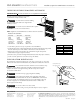
Electric Towel Warmer
Thermal Fuse
Thermostat Element
Heating Element Wiring Box
Field Wiring
L
N
GRND
L
N
GRND
Field Installed Wall Switch or
Mr. Steam Digital Programmable Timer
PN: 103588DIG
Indicator Light
X
X
X
!
WA RN IN G
!
CA UT IO N
6
Wiring Box Set Screw(s)
Wiring Box
Wiring Flange
Wiring Box
Field
Wires
W
iring Flange
BX Connector
Lock Nut
B
X Cable*
(or greenfield)
Wires from
wiring box
!
WA RN IN G
1. Assemble the BX cable
connector to the wiring
flange as shown.
NOTE: NM (non-metallic) cable,
if permitted by National and
Local Codes, may be used
instead of BX cable
2. Secure wiring flange to the
wall with screws provided.
(Use longer screws as required
by construction conditions.)
3. Connect wiring per
instructions.
4. Slide the wiring box into the
wiring flange and tighten
the set screw firmly. Secure
the upper threaded flanges
and lower bracket with screws
provided.
!
WA RN IN G
!
WA RN IN G
!
CA UT IO N