
Install Instructions
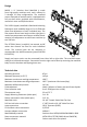
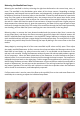

To ensure the system is installed correctly and without leaks, it is necessary to do a pressure test.
The pressure test can be done with pressurized air or water. However, due to the risk of water
freezing and damaging the system, MrPEX recommends air tesng.
To make the test, connect the MrPEX® pressure test kit with a 0÷100 psi gauge and an air valve,
or other pressure test device, to the manifold. Pressure test any poron of the system that will be
embedded in the oors, walls or ceilings of the building to 40 to 60 psi or as indicated by local code,
whichever is greater, for at least 30 minutes or for a sucient period of me to determine if any
leaks appears during the test. Reduce test pressure to 30 psi prior to embedding the tubing.
A 30 to 40 psi pressure test should remain during phases of construcon to monitor system integrity.
Note 1: If tubing is to be le under pressure for a longer period, make sure to reduce the pressure
to 30 psi
Note 2: Consult local mechanical code for specic requirement in your area
Note 3: Maximum pressure during the test should not exceed 145 psi
To ensure proper performance, it is important to fully ll the system with clean water and purge all
the air contained. In case of underoor heang systems is suggested to do this operaon directly
at the manifold.
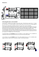
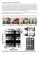
The simple steps to ll and purge the manifold are as follows:
1 - Close the supply and return ball valves of the manifold
2 - Connect a hose from a faucet to the ll valve on the supply manifold. Another hose should be connected to the
ll valve posioned on the return manifold. The end of the hose connected with the return need to be placed into
a large bucket or into a drain within view
3 - Close all owmeters and on/o valves on the manifold
4 - Open the ll valves on supply and return manifolds by using the square tool on the caps of the valves. Aer this
operaon the water lls the supply manifold but doesn’t go into the circuits because the owmeters are closed
5 - Open the owmeter and the on/o valve of the rst loop. The water ows into the circuit and pushes the air
out. Connue lling unl no more bubbles are visible in the exit water or bucket
6 - When the rst circuit is lled, close rst the on/o valve, and then the owmeter
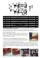
7 - Repeat steps 5 and 6 to ll and purge each manifold loop. Purging/lling one circuit at a me, ensures that all
the air gets removed from each loop
8 - When all circuits are lled, close the ll and drain valve posioned on the return manifold and subsequently
the ll and drain valve of the supply manifold. Remove the hoses from the ll valves and reposioning the safety
valve caps
9 - Open all the on/o valves and all owmeters, and then use the manual air vent on the top of each manifold
body to remove the remaining air in the manifold body
10 - Once the mains are totally lled and purged, open the manifold supply and return ball valves
Pressure Tesng the Manifold
Filling and purging the manifold