
Install Instructions


The manifold is supplied with straight full port ball valves. The ball valves come with a 1” Female
NPT connecon. It is recommended to connect the ball valves to the mains prior to connecng the
ball valves to the at gasket manifold connecon to ensure their correct orientaon.
For the NPT threads, use appropriate pipe sealer or Teon® tape, while for the at gasket connecon
between ball valves and union piece on the manifold use the rubber gaskets included in the package.
The red ball valve handle indicates supply, while the blue ball valve handle indicates return.
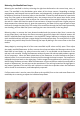
To avoid damage, the thermometers should be connected to the valve bodies when the installaon
of the manifold is completed. Connecng the ball valves should be done with an appropriate wrench
by using only the hexagonal part of the valve body.
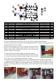
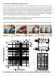
A manifold adapter part# 3250010 (G1-1/4” Flat Gasket x 1” NPT Female) set of 2, is available for
installaons where the manifold ball valves are not used. See illustraon below.
A Union Elbow Set, part# 3250007 (G1-1/4” Flat Gasket Male/Female) set of 2, is available when
supply and return mains comes from below or above. See illustraon below.
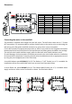
Connecng the mains to the manifold
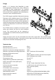
Dimensions
Part#
3250200 2 Branches
12 Branches
11 Branches
10 Branches
9 Branches
8 Branches
7 Branches
6 Branches
4 Branches
3 Branches
5 Branches
3250300
3250400
3250500
3250600
3250700
3250800
3250900
3251000
3251100
3251200
7.1
8.0
9.0
9.9
10.8
11.5
12.7
13.6
14.5
15.5
16.4
10.6”
12.6”
14.6”
16.5”
18.5”
20.4”
22.4”
24.4”
26.3”
28.3”
30.3”
Length L (inch) Weight (lb)