
Product Manual


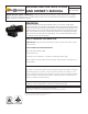
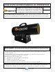


Force-Air Propane Construction HeaterOperating Instructions and Owner’s Manual
6
Ifanyoriginalwiringassuppliedbytheheatermustbereplaced,
itmustbereplacedwithtypeAWG105°Cwireoritsequivalent
exceptasindicated(*typeSF2-200,**SGI250°C).
170QFAVT ‑ WIRING CHART
COLOR LENGTH FROM TO
White 7” Valve TerminalBlock
Black 6” On/OffSwitch TerminalBlock
Red-(Hi-Temp) 161/2” HighLimitSwitch Valve
Red-(Hi-Temp) 161/2” HighLimitSwitch TerminalBlock
Orange 11” FlameControl SparkPlug
(Ignition)
Green 7” FlameControl Ground
(Harness)
Red 7” FlameControl TerminalBlock
(Harness)
White 6” FlameControl TerminalBlock
(Harness)
Black 6” FlameControl TerminalBlock
(Harness)
HOW MUCH HEAT DO I REQUIRE?
Foreconomy,itisimportanttomatchinputtothatrequired.But
heatrequirementsoftenvary.Forexample,itusuallytakesalot
moreheattogetthingswarmthanitdoestokeepthemthatway.
Likewise,outsideairtemperatureusuallychangesduringtheday
soyoumayneedmoreheatatnightthanyoudointhedaytime.
Anapproximationoftheheatrequiredcanbefoundbyusingthe
chartbelow.
Recommended Minimum Gauge
for Cord Extensions
Wire Gauge Chart A.W.G.
Name
Plate 120V Cord Length in Feet
Amps. 25 50 100 150
5-6 18 16 14 12
6-8 18 16 12 10
8-12 18 14 12 10
10-12 16 14 10 8
12-14 16 12 10 8
WARNING: Whenusingathermostatcontrolledheater,
itsexitareashouldbeprotected frompersonneland
warningspostedofsuddenstartup.
Cubic feet Temperature Rise Required (
o
F)*
of space to
be heated 20
o
30
o
40
o
50
o
5,000 14,000 20,000 27,999 34,000
7,000 19,000 28,000 38,000 47,000
10,000 27,000 40,000 54,000 67,000
15,000 40,000 60,000 80,000100,000
20,000 54,000 80,000107,000133,000
30.000 80,000120,000160,000200,000
50,000133,000200,000266,000333,000
BTU’S PER HOUR REQUIRED
HIGH-LIMIT
SWITCH X2
LINE
VALVE
NEUT
GRD
CHASSIS
GROUND
CHASSIS
GROUND
CHASSIS
GROUND
CHASSIS
GROUND
CHASSIS
GROUND
LINECORD
THERMOSTAT
MOTOR
GAS
VALVE
FLAMECONTROL
SPARKPLUG
G
W
G
G
B
B
B
B
R
W
W
R
Y
B
Y
G
G
WIRING DIAGRAM
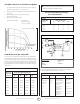
SIZE AND CAPACITY OF PROPANE CYLINDERS
Thechartsbelowshowtheapproximatesizeofthecylinder
requiredfortheseheaters.Tousethechart:
1. Selectthelowestairtemperatureexpected(atthebottomof
thechart).
2. Movestraightuptotimeofoperationdesired
(leftsideofthechart).
3. Readthecylindersizerequired.
Allheatersshouldhave: fullcylinders
goodaircirculation
nofrostoncylinders
FuelCyclinderCapacity:100#
COLORCODE
B-BLACK
L-BLUE
G-GREEN
O-ORANGE
R-RED
W-WHITE