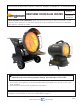
OPERATING INSTRUCTIONS AND OWNER’S MANUAL KEROSENE FORCED-AIR HEATER Model # MH125KTFR MH70KTFR READ INSTRUCTIONS CAREFULLY: Read and follow all instructions. Place instructions in a safe place for future reference. Do not allow anyone who has not read these instructions to assemble, light, adjust or operate the heater. WARNING: If the information in this manual is not followed exactly, a fire or explosion may result causing property damage, personal injury or loss of life.
WARNING: WARNING: YOUR SAFETY IS IMPORTANT TO YOU AND TO OTHERS, SO PLEASE READ THESE INSTRUCTIONS BEFORE YOU OPERATE THIS HEATER. NOT FOR HOME OR RECREATIONAL VEHICLE USE WARNING: GENERAL HAZARD WARNING: FIRE, BURN, INHALATION, AND EXPLOSION HAZARD.
SPECIFICATIONS CAUTION: CSA certified for use with only No. 1-K kerosene fuel. Factory Tested: Kerosene, Diesel #1 and #2, Fuel Oil #1 and #2, JP8 (Jet A Fuel) Model MH125KTFR MH70KTFR BTU 125,000 BTU/HR. 70,000 BTU/HR. .96 GAL/HR. .52 GAL/HR. 9.25 GALLONS 2.77 GALLONS 10 HRS. 5.34 HRS. CONSUMPTION RATE TANK CAPACITY RUN TIME ELECTRICAL DATA 120v 60Hz 120v 60Hz 22.5” X 34.5” X 38” 13.25” X 25” X 22.25” DRY WEIGHT 66 LBS. 40 LBS. FULL WEIGHT 129 LBS. 58.89 LBS.
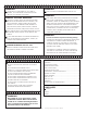
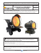
3. Next install the heat shields. These are attached centered at the 12 o’clock and 6 o’clock positions. The larger one will be installed at the bottom. These are fastened into place using the screws holding the radiant heating surface plate in place. Simply loosen only the necessary screws attach the shields and tighten the screws back into place. MH70KTFR 1. First Locate the hardware package. You will find four long screws for the base tubing, along with 4 nuts and washers.
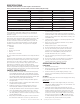
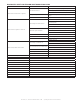
DIAGNOSTIC SAFETY SHUTDOWN AND TROUBLE SHOOTING FAULT CAUSE SOLUTION Check power supply (is it plugged in?) No electrical current Motor does not start and no ignition Check proper position of the switch (is it on?) Check fuse/breaker Wrong setting on thermostat Check for setting of thermostat higher than room temp. Defective motor Replace Motor Ensure an adequate level of fuel is in the tank. Not enough fuel at the burner Cycle unit a few time to allow fuel to fill the filter and fuel system.
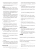
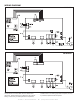
WIRING DIAGRAM MH70KTFR MH125KTFR setting, have it checked. A heater which is not working right must be repaired, but only by a trained, experienced service person. The parts lists and wiring diagram show the heater as it was constructed. Do not use a heater which is different from that shown. Heater performance is effected by air pressure setting. If there is any uncertainty about the air pressure Mr. Heater, Inc.
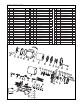
EXPLODED VIEW # P/N MH70KTFR QTY # P/N QTY # P/N Oil drain Plug 1 22 N/A Air Collection ring 1 43 22342 N/A Drain plug O-ring 1 23 N/A Seal plate 1 44 22302 Tank support foot 1 24 22323 Nozzle 1 45 4 22303 Fuel tank 1 25 22324 Swirl plate 1 5 22304 Fill spout filter holder 1 26 N/A Burner head 1 6 22305 Fill spout Filter 1 27 22326 Igniter 7 22306 Fuel cap 1 28 22327 8 N/A Spring clamp 1 29 9 N/A Fuel return line o-ring 1 10 22308 Fu
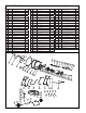
EXPLODED VIEW # P/N 1 N/A 2 22363 3 N/A 4 22364 5 N/A MH125KTFR QTY # P/N QTY # P/N Wheel retention nut DESC. 2 25 N/A Left frame panel DESC.
OPERATING INSTRUCTIONS AND OWNER’S MANUAL Model # MH70KTFR MH125KTFR WARNING: USE ONLY MANUFACTURER’S REPLACEMENT PARTS. USE OF ANY OTHER PARTS COULD CAUSE INJURY OR DEATH. REPLACEMENT PARTS ARE ONLY AVAILABLE DIRECT FROM THE FACTORY AND MUST BE INSTALLED BY A QUALIFIED SERVICE AGENCY. PARTS ORDERING INFORMATION: PURCHASING: Accessories may be purchased at any Mr. Heater local dealer or direct from the factory FOR INFORMATION REGARDING SERVICE Please call Toll-Free 800-251-0001 www.mrheater.
MANUEL DE L’UTILISATEUR ET INSTRUCTIONS D’OPÉRATION RADIATEUR AU KÉROSÈNE À VENTILATION FORCÉE No de modèle MH125KTFR MH70KTFR LIRE ATTENTIVEMENT CES INSTRUCTIONS : Lire et suivre toutes les instructions. Placer ces instructions dans un endroit sûr pour référence future. Ne pas permettre à quiconque qui n’aurait pas lu ces instructions de procéder à un assemblage, un ajustement ni au fonctionnement de ce radiateur.
AVERTISSEMENT : AVERTISSEMENT : VOTRE SÉCURITÉ EST IMPORTANTE POUR VOUS ET POUR LES AUTRES, PAR CONSÉQUENT VEUILLEZ LIRE CES DIRECTIVES AVANT DE FAIRE FONCTIONNER CE RADIATEUR. CET APPAREIL N’EST PAS CONÇU POUR UTILISATION DANS UNE RÉSIDENCE OU DANS UN VÉHICULE RÉCRÉATIF.
SPÉCIFICATIONS MISE EN GARDE : Homologué CSA pour utilisation seulement avec du kérosène no 1-K.
3. Ensuite, installer les protecteurs thermiques. Ils sont fixés et centrés aux positions correspondant à 12 heures et 6 heures. Le plus gros doit être installé au bas. Ils doivent être fixés en place à l’aide de la vis qui retient la plaque de la surface de chauffage radiant. Desserrer simplement seulement la vis nécessaire et fixer les protecteurs et resserrer la vis en place. MH70KTFR 1 Localiser d’abord l’ensemble de quincaillerie.
DÉPANNAGE ET DIAGNOSTIQUE EN CAS D’EXTINCTION DE SÉCURITÉ FAUTE CAUSE SOLUTION Vérifier l’alimentation (bien connectée?) Pas de courant électrique Le moteur ne démarre pas et il n’y a pas d’ignition Vérifier la bonne position du commutateur (allumé?) Vérifier le fusible/disjoncteur Mauvais réglage sur le thermostat Vérifier si le réglage du thermostat est plus élevé que la température de la pièce Moteur défectueux Remplacer le moteur S’assurer qu'il y a un niveau adéquat de carburant dans le réservo
WIRING SCHÉMA DEDIAGRAM CÂBLAGE MH70KTFR DEL AFFICHAGE À DEL TÉMOIN LUMINEUX -R1 PLAQUETTE DU PANNEAU NTC1 THERMOSTAT (CONTRÔLE DE TEMPÉRATURE) LIMITE 1 HS- capteur d’effet Hall PH- photocellule TP- sonde de température LIMITE 2 SW- commutateur ST- thermostat de sécurité VALVE POMPE VENTILATEUR 1 VENTILATEUR 2 IGNITION Interrupteur anti-basculement MH125KTFR DEL AFFICHAGE À DEL PLAQUETTE DU PANNEAU THERMOSTAT (CONTRÔLE DE TEMPÉRATURE) HS- capteur d’effet Hall PH- photocellule TP- sonde de
VUE ÉCLATÉE No MH70KTFR DESC. QTÉ No No de Pièce Bouchon de vidange d’huile 1 22 S/O Joint torique du bouchon de vidange 1 23 S/O No de Pièce DESC. QTÉ No No de Pièce Anneau du collecteur d’air 1 42 22341 Plaquette de contrôle du thermostat DESC.
VUE ÉCLATÉE No DESC. QTÉ No QTÉ No No de Pièce Écrou de retenue de la roue 2 24 S/O Châssis tubulaire de gauche 1 48 S/O Roue 2 25 S/O Panneau gauche du châssis 1 49 22334 Espaceur de roue 2 26 S/O Bouton d’ajustement d’angle 2 50 S/O Essieu 1 27 S/O Vis pivot 2 51 22327 Goupille fendue 2 28 22371 Poignée de transport 1 52 S/O No de Pièce 1 S/O 2 22363 3 S/O 4 22364 5 S/O MH125KTFR DESC. No de Pièce DESC.
INSTRUCTIONS DE FONCTIONNEMENT ET MANUEL DE L’UTILISATEUR No de modèle MH70KTFR MH125KTFR AVERTISSEMENT : UTILISER SEULEMENT LES PIÈCES DE RECHANGE DU FABRICANT. L’UTILISATION DE TOUTE AUTRE PIÈCE PEUT CAUSER DES BLESSURES OU UN DÉCÈS. LES PIÈCES DE RECHANGE SONT DISPONIBLES SEULEMENT DIRECTEMENT DE L’USINE, ET ELLES DOIVENT ÊTRE INSTALLÉES PAR UNE AGENCE QUALIFIÉE DE SERVICE.
INSTRUCCIONES DE USO Y MANUAL DEL USUARIO CALEFACTOR DE AIRE FORZADO A KEROSENE Modelo # MH125KTFR MH70KTFR LEA CUIDADOSAMENTE LAS INSTRUCCIONES: Lea y siga todas las instrucciones. Conserve estas instrucciones en un lugar seguro para futura referencia. No permita que nadie que no haya leído estas instrucciones arme, encienda, ajuste o use el calefactor.
ADVERTENCIA: ADVERTENCIA: SU SEGURIDAD ES IMPORTANTE PARA USTED Y PARA LOS DEMÁS, ASÍ QUE POR FAVOR LEA ESTAS INSTRUCCIONES ANTES DE UTILIZAR EL CALEFACTOR. NO APTO PARA USAR EN EL HOGAR NI EN CASAS RODANTES ADVERTENCIA: ADVERTENCIA GENERAL DE PELIGRO: PELIGRO DE INCENDIO, QUEMADURAS, INHALACIÓN Y EXPLOSIÓN. MANTENGA LOS COMBUSTIBLES SÓLIDOS, TALES COMO MATERIALES DE CONSTRUCCIÓN, PAPEL O CARTÓN, A UNA DISTANCIA SEGURA DEL CALEFACTOR.
ESPECIFICACIONES CUIDADO: Certificado por la CSA para usar únicamente con querosene No. 1-K. Probado en fábrica: Querosene, diesel #1 y #2, aceite combustible #1 y #2, JP8 (combustible Jet A) Modelo BTU CONSUMO CAPACIDAD DEL TANQUE MH125KTFR MH70KTFR 125.000 BTU/H 70.000 BTU/H 0,96 GAL/H 0,52 GAL/H 9,25 GALONES 2,77 GALONES 10 HORAS 5,34 HORAS TIEMPO DE FUNCIONAMIENTO DATOS ELÉCTRICOS 120v 60Hz 120v 60Hz 22.5” X 34.5” X 38” 13.25” X 25” X 22.
superficies, la que tiende a aumentar luego de apagarlos. Permita que se complete este ciclo antes de desenchufar el calefactor. en Canadá, deberá instalar una cubierta contra cortinas ad¬icional por encima de la cubierta del radiador. La cubierta y los tornillos vienen incluidos. 3. Luego instale las cubiertas contra el calor. Se fijan en el centro, en las posiciones de las 12 en punto y las 6 en punto. La más grande se instala en la parte de abajo.
DIAGNÓSTICO DE APAGADO CON SEGURIDAD Y RESOLUCIÓN DE PROBLEMAS FALLA CAUSA SOLUCIÓN Revise la fuente de alimentación (¿está enchufado?) No hay corriente eléctrica El motor no enciende y no hay ignición Verifique la posición correcta del interruptor (¿está en ON?) Verifique el fusible o la llave general Ajuste inadecuado del termostato Verifique que el termostato esté ajustado más alto que la temperatura ambiente Motor defectuoso Reemplace el motor Asegúrese de que el tanque tenga suficiente combusti
DIAGRAMA DE CABLEADO WIRING DIAGRAM MH70KTFR INDICADOR LED LUZ -R1 PCB DEL PANEL NTC1 TERMOSTATO (CONTROL DE TEMP.) LÍMITE 1 HS- Sensor de efecto Hall PH- Célula fotoeléctrica TP- Sonda de temperatura SW – Interruptor LÍMITE 2 ST- Termostato de seguridad BOMBA VÁLVULA VENTILADOR 2 VENTILADOR 1 ENCENDEDOR Protección contra caídas MH125KTFR INDICADOR LED PCB DEL PANEL TERMOSTATO (CONTROL DE TEMP.
PLANO DE DESPIECE No Parte 1 22300 2 3 DESC. MH70KTFR CANT.
PLANO DE DESPIECE No DESC. Parte MH125KTFR CANT. No Parte Tuerca de retención de la rueda 2 24 N/D Rueda 2 25 Espaciador de la rueda 2 26 Eje 1 Chaveta 2 DESC. CANT.
INSTRUCCIONES DE USO Y MANUAL DEL USUARIO Modelo # MH70KTFR MH125KTFR ADVERTENCIA: USE SOLAMENTE PARTES DE REPUESTO DEL FABRICANTE. EL USO DE CUALQUIER OTRA PARTE PODRÍA CAUSAR HERIDAS O LA MUERTE. LAS PARTES DE REPUESTO ESTÁN DISPONIBLES ÚNICAMENTE EN LA FÁBRICA Y DEBEN SER INSTALADAS POR UNA AGENCIA DE SERVICIO CALIFICADA INFORMACIÓN PARA ORDENAR PARTES: COMPRAS: Puede comprar accesorios en cualquier distribuidor local de Mr. Heater o directamente de la fábrica.