
Use and Care Manual

5
Installation Instructions and Owner’s Manual
Gas Fired Infrared Space Heater
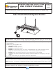
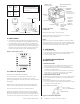
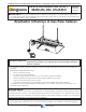
Figure 4 connection diagram
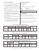
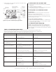
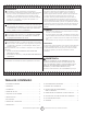
9. VENTILATION
a. Theminimumintakeandexhaustairopeningsshallprovide
fornotlessthan400CFMforevery100,000BTUinputexcept
thattheinfiltrationareamaybeincludedintheintakearea.
b. Wherenatural(gravity)ventilationisprovidedforexhaust,the
openingsmustbedistributedabovetheheaters(preferablyat
thepeakoftheroof)andtheareasofopeningsshallnotbe
lessthan300squareinchesforevery100,000BTUinput.
Figure 5. Thermostate controls
10. START-UP PROCEDURE
OPENTHEGASSUPPLYVALVEORVALVES
SetthethermostattotheOFFposition.SeeFigure5.Ifthe
manualgascontrolknobonthegasvalveisnotintheOFF
position,partiallydepresstheknobandrotatetotheOFFposition.
SeeFigure6.
Wait5minutestoallowgasthatmayhaveaccumulatedinthe
mainburnertoescape(especiallyimportantafterinstallation).
TurnthemanualgascontrolknobtothePILOTposition.
Depressthemanualgascontrolknob.Usingamatch,lightthe
pilotlight.SeeFigure6.Holdtheknobdownforapproximately
30secondstoallowanyairingaslinestopassthroughpilotand,
oncethepilotislit,allowthethermocoupletoheatupenoughto
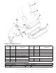
MANUALGAS
CONTROLKNOB
WRENCH
BOSS
GASINLET
PRESSUREREGULATOR
ADJUSTMENT
STANDARD
PRESSURE
REGULATOR
(Incomingpressure
notexceed14”W.C.)
PILOTGAS
OUTLET
(PRESSURE
TAPPING
DIRECTLY
BENEATH)
PILOTFLOW
ADJUSTING
SCREW
(BENEATH
COVERSCREW)
PILOTSTATPOWER
UNIT
Figure 6. Gas Valve
Components
activatethesafetyvalveinanopenposition.
ReleasemanualgascontrolknobandturntoON.Reset
thermostattodesiredtemperature.
NOTE:
DuringtheinitialstartupofMR.HEATERanodorand,perhaps,
somevaporwillcomefromtheheater.Thisisthegasketbinding
materialemittingthisodorand/orvapor.Afterapproximately20
minutesthisodorwilldisappearandnotoccuragain.
11. SHUTDOWN
1. TurnthermostattoOFF.
2. TurnmanualgascontrolknobongasvalvetoPILOTposition.
3. PartiallydepressknobandrotatetotheOFFposition.
4. Closegassupplyvalves.
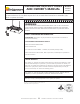
12. OPERATOR MAINTENANCE
INSTRUCTIONS
1. TROUBLESHOOTING
a. Table4liststhecommonmalfunctionswhichyoumayfind
duringtheoperationormaintenanceofyourheater.
b. ForadditionalinformationrefertoHoneywellFieldBulletin
enclosedintheheatercarton.
c. Intheevent,resultscannotbeobtainedafterperformingall
listedsolutions,callyourMr.Heaterdealer,orthefactory
customerservicedepartmentat1-800-251-0001.
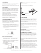
2. ADJUSTING THE PILOT FLAME
Thepilotflameshouldenvelope3/8to½in.(10to13mm)ofthe
tipofthethermocoupleorgenerator.Toadjustthepilotflame,
refertoFigure7.
a. Removepilotadjustmentcoverscrew.RefertoFigure8.
b. Turninneradjustmentscrewclockwisetodecreaseorcounter-
clockwisetoincreasepilotflame.
THERMOCOUPLE
PROPERFLAMEADJUSTMENT
3/8TO½INCH
(10TO13MILLIMETERS)
Figure 7. Proper flame adjustment
POWERPILEGASVALVE
POWERPILEGENERATOR
WIRE
SIZES
MAXIMUM
LENGTH
2WIRE
CABLE
NO.18
NO.16
NO.14
15FEET
30FEET
50FEET
CAUTION:
Neverconnectpowerpilegas
valveorthermostattolinevoltage
oratransformer
FactoryWired
ThermostatWires