
Specifications


© The Fulton Companies 2012
4-4
MAINTENANCE VTG-IOM-2012-1001 SECTION 4
4 CAUTION
All information in this manual is for
reference and guidance purposes,
and does not substitute for required
professional training, conduct,
and strict adherence to applicable
jurisdictional/professional codes and
regulations.
All maintenance procedures should
be completed by trained personnel.
Appropriate training and instructions
are available from the Fulton Service
Department at (315) 298-5121 or
your local Fulton Heating Solutions
Representative.
In order to meet warranty conditions,
ensure all appropriate maintenance
activities are performed.
5. Leak test the gas valves.
6. Test relief valve per manufacturer instructions by lifting the lever for 5
seconds and allowing the valve to snap shut. Please see the manufacturer’s
recommendations on the relief valve tag.
Verifi cation of Torque Settings on Fireside Access
Doors
NOTE: ´ This section is relevant to Models VTG-4000LE, VTG-4000DF, VTG-5000DF,
and all standard VTG-4000 and VTG-5000 units starting with National Board #
7618 or shipped after June 14, 2012.
There are two access doors to the reside of the heat exchanger of the above
referenced Vantage models. There are a series of bolts on each door that must
be checked for torque every 2,500 operating hours, or once per heating season
(whichever is more frequent).
Proceed as follows:
1. Remove the boiler jacket panels (upper and lower) on the front of the
boiler.
2. Verify settings of the upper door. The upper door is retained by (4) 1-1/8”
bolts. Tools required for upper door setting veri cation:
§ 1-13/16” socket and ¾ x ½” adapter (these were provided from
the factory and should be stored in a safe place in the boiler
room). If these components have been misplaced, please
contact Fulton to purchase replacement components. The
Fulton part numbers are 2-22-000570 (socket) and 2-22-000571
(adapter).
§ ½” drive torque wrench and extension (provided by service
technician)
NOTE: ´ The upper door has a mass of approximately 140 lbs. Do not remove
the (4) bolts or door without guidance from the factory with regards to proper
procedures for accessing the reside of the heat exchanger.
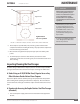
3. Evenly tighten all 4 bolts on the upper door in three stages: rst to 20 ft/
lbs, then to 35 ft/lbs, then to 50 ft/lbs in the following criss-cross pattern:
top left, bottom right, bottom left, top right. Recheck all bolts in a circular
pattern. See Figure 15.
4. Verify settings of the lower door. The lower door is retained by (16) 9/16”
bolts. Tools required for lower door setting veri cation:
§ 9/16” socket and 3/8” drive wrench (provided by service
technician)
5. Evenly tighten all 16 bolts on the lower door to 23 ft/lbs in a criss-cross
pattern. See Figure 15. Do not over torque, as this can result in damaging
of the door seal.