
Specifications


Questions? Call (315) 298-5121, or visit us online at www.fulton.com
2-27
SECTION 2 VTG-IOM-2012-1001 INSTALLATION
5. Test for spillage at the draft hood relief opening after 5 minutes of main
burner operation. Do not use the ame of a match or candle or smoke
from a cigarette, cigar or pipe.
6. After it has been determined that each appliance remaining connected
to the common venting system properly vents when tested as outlined
above, return doors, windows, exhaust fans, replace dampers and any
other gas-burning appliance to their previous conditions of use.
7. Any improper operation of the common venting system should be
corrected so the installation conforms with the National Fuel Gas Code,
ANSI Z223.1. When resizing any portion of the common venting system,
the common vent system should be resized to approach the minimum size
as determined using the appropriate tables.
Electrical Connections
Motors are designed to operate within the following limits at the motor
terminals: AC power supplied is within +/- 10% of the motor rated voltage
with the rated frequency applied; or AC power supplied is within +/- 5% of the
rated frequency and with the rated voltage; or a combined variation in voltage
and frequency of +/-10% (sum of absolute values) of rated values provided the
frequency variation does not exceed +/-5% of rated frequency. For 3-phase
motors, the line to line full voltage must be balanced within 1% of the rated
motor voltage. If the motor is rated 208-230V, the voltage deviations must
be calculated from 230V. Operation outside these limits will degrade motor
performance. 575V rated motors cannot be operated at voltages above 600V.
Depending on motor manufacturer, a 208V rated motor may not be able to run
below the design voltage.
Adhere to the following when making electrical connections:
1. Install wiring and ground in boiler in accordance with authority having
jurisdiction or in absence of such requirements National Electrical Code,
ANSI/NFPA 70.
NOTE: ´ Connect a ground wire to green colored ground lug in electrical control
box.
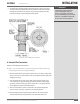
2. Review the electrical schematic diagram. Vantage boilers are available
with a variety of 3 phase electrical con gurations. Step-down transformers
are provided as standard with every boiler. Each boiler is shipped with its
own unique electrical schematic diagram, a copy of which is located in an
envelope on the inside door of the panel box.
3. Connect power to the terminal strip as supplied on the inside of the panel
box.
! WARNING
All information in this manual is for
reference and guidance purposes,
and does not substitute for required
professional training, conduct, and strict
adherence to applicable jurisdictional/
professional codes and regulations.