
Specifications


Questions? Call (315) 298-5121, or visit us online at www.fulton.com
2-25
SECTION 2 VTG-IOM-2012-1001 INSTALLATION
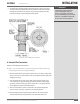
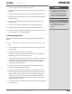
5. Install two pipe retaining clamps around the intake as well as vent pipes
on both ends of the wall thimble (on the inside and outside of the wall)
through which intake and vent pipes are passed. They will prevent the
intake and vent pipes from being pushed or pulled.
¡ Horizontal Vent Termination
Adhere to the following for installation:
NOTE: ´ The vent termination is joined to the vent pipe outside the wall. Use the
same joining procedures for vent pipe and ttings.
1. The termination of the vent system must be at least 12” above the nished
grade, or at least 12” above normal snow accumulation level (for applicable
geographical areas).
2. The termination of the vent system shall not be located in tra c areas
such as walk ways, adjacent buildings, operable windows and building
openings unless the venting system is at least 7 ft (2.1 m) above nished
grade, (National Fuel Gas Code, ANSI Z223.1).
3. The vent terminations must be at least 4 ft (1.22 m) horizontally from
electric meters, gas meters, regulators, and relief equipment.
4. When installing inlet and exhaust terminations on the same wall, the
exhaust outlet must be installed 4 ft (1.22 m) minimum above and
! WARNING
All information in this manual is for
reference and guidance purposes,
and does not substitute for required
professional training, conduct, and strict
adherence to applicable jurisdictional/
professional codes and regulations.
FIGURE 14 - WALL THIMBLE INSTALLATION