
Specifications


© The Fulton Companies 2012
2-22
INSTALLATION VTG-IOM-2012-1001 SECTION 2
NOTE: ´ Consider all possible draft conditions (based on the modulation and
quantity of the boilers). When doing pressure drop calculations for a system of
boilers sharing air intake or exhaust piping, it is important for the designer and
provider of the draft system to consider the full scope of possibilities that can be
experienced by that system. This includes looking at the condition of one boiler on
at a low re condition and all units on at a high re condition.
¡ Venting Terminations
Adhere to the following for installation:
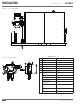
1. All vent pipes and ttings must be installed with appropriate air space
clearances to combustibles. These air space clearances apply to indoor or
outdoor vents—whether they are open, enclosed, horizontal or vertical
or pass through oors, walls, roofs, or framed spaces (See Figures 12 and
13). The air space clearances should be observed to joists, studs, sub
oors, plywood, drywall or plaster enclosures, insulating sheathing, rafters,
roo ng, and any other material classed as combustible.
2. The required minimum air space clearances also apply to electrical wires
and any kind of building insulation.
3. Adequate provision must be made to support the weight of the exhaust
venting. It cannot be supported by the boiler exhaust connection.
4. Listed termination parts must be used.
5. Select the air intake point of penetration where a minimum of 1/4” per foot
upward pitch can be maintained.
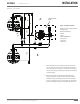
6. When penetrating a non-combustible wall, the hole through the wall must
be large enough to maintain the pitch of the vent and provide sealing. Use
adhesive material to seal around the vent on both sides of the wall. When
penetrating a combustible wall, a wall thimble must be used. See Figure 13
for installation instructions. Minimum wall thickness through which vent
system may be installed is 3.25”. Maximum wall thickness through which
vent system may be installed is 20 inches.
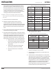
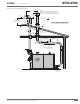
¡ Wall Thimble Installation
Adhere to the following for installation (see Figure 14):
1. The thimble is inserted through the wall from the outside.
2. Secure the outside ange to the wall with nails or screws, and seal with
adhesive material.
3. Install the inside ange to the inside wall, secure with nails or screws, and
seal with adhesive material.
4. Pass the vent pipe through the thimble from the outside and join to the
rest of the vent system. Seal the pipe to the thimble ange with adhesive
material.
! WARNING
All information in this manual is for
reference and guidance purposes,
and does not substitute for required
professional training, conduct, and strict
adherence to applicable jurisdictional/
professional codes and regulations.