
Specifications


Questions? Call (315) 298-5121, or visit us online at www.fulton.com
2-21
SECTION 2 VTG-IOM-2012-1001 INSTALLATION
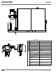
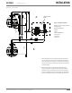
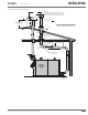
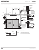
¡ Common Venting Layouts for Vantage
It is possible to combine the air intake and/or exhaust piping for a number of
Vantage boilers. The pressure drop across the common system (combined total
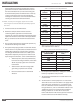
for air intake and exhaust) cannot exceed the pressure drop requirements for an
individual boiler. See Table 4.
Adhere to the following for installation:
1. Consult your venting supplier for guidance in designing common vented
installations. It is imperative to design such systems to prevent back ow of
exhaust gases through idle boilers.
2. Vantage boilers cannot be common vented with other equipment.
When designing a draft system for a quantity of two or more Vantage boilers, the
following items must be considered and addressed by the parties responsible for
designing and providing that system:
} MULTIPLE BOILERS SHARING AN EXHAUST STACK, NEGATIVE PRESSURE IN THE
COMMON HEADER:
1. Precautions must be taken to ensure that the negative pressure in the
common header stays within the stated ranges (refer to table 4) at all
possible conditions. This includes considering all possible operating
conditions of the stack, including:
§ All boilers on at their maximum input rating capacity
§ One boiler in the system on at a low re position
§ No boilers on, light o condition
2. Draft accessories, such as stainless steel dampers, may be required
depending on the variety of conditions experienced in the draft system.
} MULTIPLE BOILERS SHARING AN EXHAUST STACK, POSITIVE PRESSURE IN THE
COMMON HEADER:
1. Precautions must be taken to ensure the prevention of ue gases from
traveling back through idle boilers ( ue gas recirculation, FGR). Looking
at the condition of all boilers on at high re condition will facilitate the
selection of the diameter of the stack that is appropriate; however there is
still a risk of FGR that needs to be managed. Options to consider for this
management include the following:
§ Mechanical draft assist systems (exhaust fans).
§ Stainless steel dampers installed in the individual stack sections prior to
the common header connection. Damper must be controlled so that
it will close when a boiler is disabled or idle.
§ Other solutions can be considered as long as the precautions to prevent
FGR have been thoroughly evaluated.
! WARNING
The exhaust vent installer should be
familiar with Federal Codes as well
as local codes and regulations.
4 CAUTION
To prevent the possible re-circulation
of ue gases, the vent designer must
take into consideration such things
as prevailing winds, eddy zones,
building con gurations, etc. It is the
responsibility of the installer to locate
the exhaust duct in such a way that it
does not become blocked due to snow,
ice, and other natural or man-made
obstructions.
Do not locate the vent termination too
close to shrubbery as ue products may
stunt their growth or kill them.