
Specifications


© The Fulton Companies 2012
INSTALLATION VTG-IOM-2012-1001 SECTION 2
2-14
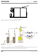
Install Oil Piping
¡ Oil Piping (For Dual Fuel Boilers with the Riello
Burner)
Adhere to the following for dual fuel boilers with the Riello
Burner (see Figure 8):
1. The Vantage dual fuel boiler is suitable for ring light
distillate fuel oil, commonly known as #2 fuel oil only.
DO NOT USE GASOLINE, CRANKCASE OIL OR ANY OIL
CONTAINING GASOLINE. If in doubt, contact your Fulton
representative prior to operation.
2. Fuel pipes must be of approved materials and of a
diameter suitable for the quantity of oil being delivered
to the burner and the static head available. A stop
valve and re valve assembly should be supplied by
the client/contractor. In addition a check valve must be
tted into the return pipe.
3. Be sure to install a foot valve as indicated in Figure 8.
The foot valve is a check valve for the oil line between
the oil pump on the boiler and the supply tank. The foot
valve keeps the oil line charged at all times.
4. The maximum pressure allowed at the fuel oil pump
inlet is limited to 3 PSIG by the National Fire Protection
Association (NFPA). If the fuel supply can exceed this
maximum, a regulator must be installed. The minimum
pressure at the pump inlet should never exceed 10” of
vacuum.
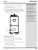
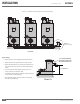
5. The oil pump (Figure 9) on the Vantage boiler is a
SUNTEC model AJ4CC or acceptable alternate. See
Figure 7. No settings are required for the pump, which
is set to 198-200 PSI by the manufacturer. This pressure
must be checked and adjusted (if required) after the
burner has been ignited. There is a pressure gauge
provided with the oil pump assembly on the boiler so
pressure can be monitored.
6. The oil piping system should be a 2-pipe system. The
delivery rate of oil to the boiler will be greater than the
fuel consumption rate of the boiler. The oil that is not
consumed should be returned to storage. Consult a
quali ed professional for assistance in designing and
installing oil delivery systems. See Figure 10.
7. Fuel Supply: The pumping unit of the burner is
equipped with a self-priming pump, which is capable
of feeding itself within the limits listed in the table in
Figure 9.
8. It’s good practice to ensure that the return and suction
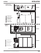
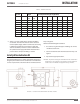
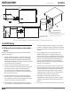
TOP VIEW
30 3/8
[771]
12 1/2
[318]
3 13/16
[97]
(TYP.)
FRONT VIEW
1 1/2" PLASTIC FITTING
CONNECTION TO DRAIN
1" NPT
CONNECTION
TO BOILER
10 3/4
[273]
11 1/4
[286]
ISOMETRIC VIEW
2
3
1
4
3
1. Neutralizer Kit with Magnesium Oxide
2. Condensate Drain Kit Assembly
3. 1 1/2” by 3” NPT Stainless or Galvanized Nipple
4. 1 1/2” Stainless or Galvanized Union
FIGURE 7 FIELD CONNECTIONS FOR CONDENSATE DRAIN TO PH NEUTRALIZATION TANK