
Specifications


Questions? Call (315) 298-5121, or visit us online at www.fulton.com
2-11
SECTION 2 VTG-IOM-2012-1001 INSTALLATION
! WARNING
All information in this manual is for
reference and guidance purposes,
and does not substitute for required
professional training, conduct,
and strict adherence to applicable
jurisdictional/professional codes and
regulations.
Do not use matches, candles, ame or
other sources of ignition to check for
gas leaks.
4 CAUTION
Some soap used for leak testing is
corrosive to certain types of metals.
Clean all piping thoroughly after
completing the leak check.
¡ Components Requiring Ventilation to the Outdoors
Although there are custom fuel train requirements available that do not include
components requiring ventilation to the outdoors, many Vantage fuel trains
will require a vent line on the high gas pressure switch and the gas pressure
regulator.
Follow the recommendations of the manufacturer of the gas pressure regulator
for speci c instructions. General instructions include:
§ Start with the vent tapping size, and as soon as is practical increase the
pipe size one diameter.
§ For every ten feet of pipe run, increase the pipe size one diameter.
§ Protect the termination from water, dust and insects.
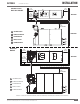
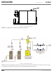
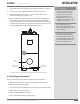
Install Condensate Drain
A condensate drain kit is intended for use with the Fulton Vantage boiler. The
Condensate Drain is Fulton Model Part Number 4-57-000440.
Adhere to the following for installation:
1. The 1” condensate drain will be connected to the 1” inlet on the drain kit.
One or more drain lines may be connected to this inlet (max of 12 MM BTU
per drain).
2. If the water supply must be temporarily disconnected, the boilers must be
turned o to prevent accidental ue gas emission into the boiler room.
3. The condensate drain cover must be kept on at all times, except during
maintenance of the drain. This drain should be checked regularly in your
boiler maintenance schedule.
4. A condensate collecting tank and condensate pump will be required if a
oor drain is not available to collect condensate (collecting tank and pump
are not supplied with the boiler).
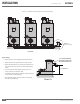
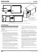
5. All piping (Figure 5) must be galvanized, or stainless steel and should
be free of leaks. Copper, carbon steel/iron pipe, PVC or CPVC are not
acceptable.
6. Connect 1” condensate drain(s) (at the rear of the boiler), to the 1” inlet at
the base of the drain tank. The bottom of the drain kit must be a minimum
of 5.5” lower than the bottom of the boiler when connected in a manifold
as shown in Figure 5, the manifold must be 5.5” below the condensate
outlet and must remain ooded.
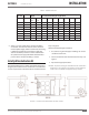
7. Connect the 1.5” drain outlet to an appropriate waste line following
applicable codes. The 1.5” drain connection on the drain tank must be the
highest point prior to going to the drain. Failure to keep drain piping lower
than this point will result in over ow of the drain tank. Slope the drain pipe
away at a minimum pitch of 1 inch (25.4 mm) for every 12 feet (3.65 m).