
Specifications


© The Fulton Companies 2012
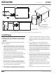
INSTALLATION VTG-IOM-2012-1001 SECTION 2
2-10
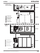
¡ Eliminate System Air
NOTE: ´ There are no built-in boiler air eliminating features.
Adhere to the following for air elimination:
1. The installation of an air separator and air eliminator (air
vent) is required.
2. To prevent scale corrosion in boiler and associated
piping, make up water must be kept to a minimum. This
is best achieved by ensuring immediate repair of all
leaks and that system pressure is maintained.
3. If a sealed diaphragm-type expansion tank is used,
install an air eliminator in the hot water piping at the air
separator.
4. If an air cushion type expansion tank is used, pipe tank
directly into boiler supply.
5. On multi-zoned systems (or a system with both space
and domestic water heating), air elimination must be
provided either in the common piping or on every loop.
6. When the boiler is installed at a higher level than
baseboard radiation (if used), air elimination must be
provided directly above the unit.
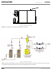
Fill the Boiler With Water
To be sure that the boiler is not air-bound, open the pressure-
relief valve located at the rear of the boiler. Leave the relief
valve open until a steady ow of water is observed. Close the
valve and nish lling the system.
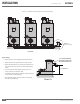
Install Gas Piping
The Vantage boiler is factory test red and combustion is
adjusted per the boiler data plate and test re sheet.
The gas train components are UL-795 certi ed to operate at
speci c gas pressure requirements. The speci c requirements
for each boiler are called out on the boiler nameplate, located
on the back of the boiler. Parameters depend on fuel(s) for
which the boiler is designed.
Adhere to the following for gas piping installation:
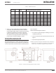
1. See Table 3 for required natural gas pipe size, based on
overall length of pipe from the meter plus equivalent
length of all ttings. Approximate sizing may be based
on 1,020 BTU for 1 cubic foot of natural gas.
2. Piping must be installed such that no piping stresses
are transmitted to the boiler. The boiler cannot be used
as a pipe anchor.
3. The boiler and all gas piping connections must be
pressure-tested and checked for leaks before being
placed into service. Test with compressed air or inert
gas if possible.
4. The boiler must be disconnected at the boiler manual
shuto valve (located at the end of the supplied gas
train) from the gas supply piping system during any
pressure testing of the system at pressures in excess of
1/2 psig (14 inch W.C.).
5. Gas Piping must be installed in accordance with
National Fuel Gas Code, ANSI Z223.1 1991 or latest
addenda and any other local codes, which may apply.
6. The pipe and the ttings used must be new and free of
dirt or other deposits.
7. Piping must be of the proper size to ensure adequate
gas supply. A drip leg and union connection must be
installed upstream of the gas safety shut o valves and
must be a 5 inch (127 mm) minimum length.
8. Connect gas supply line to the open end of the tee on
which the drip leg is installed.
9. When making gas-piping joints, use a sealing
compound resistant to lique ed petroleum gases. Do
not use Te on tape on gas line threads.
10. After gas piping is completed and before wiring
installation is started, carefully check all piping
connections, (factory and eld), for gas leaks. Use a soap
and water solution.
11. The boiler must be disconnected at the boiler shut o
valve from the gas supply piping system during any
pressure testing of the system.
NOTE: ´ The vent line connection on the gas pressure regulator
must be piped to outdoor air by the installer in accordance
with the National Fuel Gas Code, ANSI Z223.1-1991 or latest
addenda. In Canada gas installations must by in accordance
with the current CAN/CSA B149.1 and 2 and/or local codes.