
Specifications


Questions? Call (315) 298-5121, or visit us online at www.fulton.com
2-7
SECTION 2 VTG-IOM-2012-1001 INSTALLATION
! WARNING
All information in this manual is for
reference and guidance purposes,
and does not substitute for required
professional training, conduct,
and strict adherence to applicable
jurisdictional/professional codes and
regulations.
The discharge from the safety relief
valve must be arranged to ensure
no danger of scalding personnel, or
equipment damage.
Provisions must be made to properly
pipe the safety relief discharge
away from the boiler to the point of
discharge.
No shuto of any kind shall be placed
between the safety relief valve
and the boiler, or in the discharge
pipe between the valve and the
atmosphere. Doing so may cause an
explosion from overpressure.
The hydronic system should never be
ushed while the boiler is attached
to the system since the debris could
accumulate in the boiler and block
water from passing through the heat
exchanger.
Ensure all labels on the boiler are
legible. All connections and safety
devices, both mechanical and
electrical, must be kept clean, with
ease of access for inspection, use and
maintenance.
Do not store or use gasoline or other
ammable vapors and liquids or
corrosive materials in the vicinity of
this or any other appliances.
6. Install ltration to remove particulates if appropriate.
7. Install bypass chemical feeder for corrosion inhibitor maintenance if
appropriate.
8. Install corrosion coupon holder to assess corrosion inhibitor performance if
appropriate.
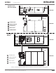
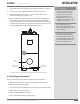
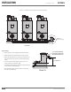
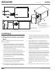
NOTE: ´ The boiler is provided with a drain valve connection and a drain valve. See
Figure 4.
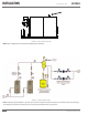
9. Before installing a Vantage boiler into a hydronic loop, be sure that the
system piping and any other components of the system are clean and
free of debris and any foreign matter. The hydronic system is completely
ushed prior to installing the boiler itself.
NOTE: ´ Although motorized isolation valves are not required in a primary only
arrangement , they can help ensure system e ectiveness. Proper control strategy
must be used to ensure ow paths in the hydronic loop and residual heat in
pressure vessel can be adequately dispersed when a boiler is disabled.
Meet Water Chemistry Requirements
System water chemistry requirements are as follows:
§ pH: Range of 8.5 - 10.5
§ Oxygen: Less than 250 ppb (operating condition)
§ Total Iron/Copper: Less than 5 ppm
§ Corrosion Inhibitor: Capable of maintaining iron corrosion rates <2
mpy. Due to changing environmental restrictions a non-heavy metal
ALL ORGANIC inhibitor is recommended which is designed for multi
metal systems including ferrous metals and yellow metals such as
copper and brass.
§ Chloride: Less than 250 ppm
Adhere to the following:
1. Refer to your water conditioning or chemical treatment supplier for
analysis and recommendations for proper system conditions.
2. Follow a program with appropriate monitoring and maintenance of system
water conditions as provided by your water conditioning or chemical
treatment supplier.
3. If RO/DI water is used as a source for hydronic loop water or makeup water,
it must be neutralized to a pH of 8.5 - 10.5 prior to entering the boiler.
Failure to neutralize the RO/DI water will void the pressure vessel warranty
and may cause high general corrosion rates.