
Specifications


© The Fulton Companies 2012
INSTALLATION VTG-IOM-2012-1001 SECTION 2
2-4
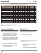
TABLE 1 BOILER DIMENSIONS AND OPERATING REQUIREMENTS
MODEL VTG
2000 2000DF 2500 2500DF 3000 3000DF 3500 3500DF 4000 4000DF 5000 5000DF 6000 6000DF
Speci cations
2000LE 3000LE 4000LE
Input Million BTU/Hr.
2 2 2.5 2.5 3 3 3.5 3.5 4 4 5 5 6 6
Fuel Cons. @ rated cap: (Nat. Gas) FT3/Hr.
2,000 2,000 2,500 2,500 3,000 3,000 3,500 3,500 4,000 4,000 5,000 5,000 6,000 6,000
Fuel Cons. @ rated cap.: (#2 Oil) GPH
NA 14.3 NA 14.3 NA 21.4 NA 21.4 NA 28.6 NA 28.6 NA 42.8
Output at AHRI Test Condition BHP
57 57 69 69 86 86 96 96 116 116 138 138 168 168
Electrical Req. (Amps) 230V, 60Hz, 3 Phase
6.8 13.4 12.9 16.1 12.9 16.1 18.5 16.1 18.5 16.1 23 29.2 23 29.2
460V, 60Hz, 3 Phase
3.4 6.7 6.5 8.1 6.5 8.1 9.3 8.1 9.3 8.1 11 16.6 11 16.6
Water Content Gal
147 147 147 147 215 215 215 215 275 275 275 275 480 480
Dry Weight LB
3,800 3,800 3,800 3,800 5,200 5,200 5,200 5,200 5,800 5,800 5,800 5,800 8,000 8,000
Operating Weight LB
5,100 5,100 5,100 5,100 7,000 7,000 7,000 7,000 8,100 8,100 8,100 8,100
12,000 12,000
Dimensions
A. Boiler Width IN
30.5 33.6 30.5 33.6 34.6 34.5 34.6 34.5 40.5 40.5 40.5 40.5 48.5 48.5
B. Overall Boiler Height IN
76 72.8 76 72.8 83.9 76.1 83.9 76.1 87.6 79.5 87.6 79.5 85.5 85.5
C. Overall Boiler Depth IN
108 120 108 120 120 132 120 132 126 136 136 136 165 165
D. Flue Outlet Diameter IN
10 10 10 10 12 12 12 12 14 14 14 14 14 14
E. Air Inlet Diameter IN
8 10 8 10 10 10 10 10 12 12 12 12 12 12
F. Water Inlet/Outlet Diameter IN
4 4 4 4 4 4 4 4 6 6 6 6 6 6
G. Min. Clearance to Ceiling IN
24 24 24 24 24 24 24 24 24 24 24 24 24 24
H. Overall Height (w/o blower) IN
68.1 68.1 68.1 68.1 76.2 76.2 76.2 76.2 79.5 79.5 79.5 79.5 85.5 85.5
* Alternate gas pressure arrangements may apply. Please verify gas pressure ratings for your boiler by viewing the boiler name plate.
** Typical 120 VAC controls allow for a +10% and a -15% voltage uctuation.
***Standard con gurations. Alternate voltages available as an option; please consult factory.
Note: All dimensions are subject to change.
Clearances and Serviceability
Adhere to the following for clearances and serviceability:
1. All local and national codes (NFPA, ANSI, UL, CSA,
ASME) must be followed for proper clearances and
serviceability for your boiler or heater. Authorities
having jurisdiction should be consulted before
installations are made.
2. Appropriate front, back, side and top clearances must
be maintained (Figure 1). This will allow access around
the equipment to facilitate maintenance and a safe
work environment. An 1 inch (25.4 mm) side clearance
is acceptable between boilers. Custom con gurations
may not allow 1 inch (25.4 mm) side clearance.
3. Ensure all labels on the boiler will be fully visible for
maintenance and inspection.
4. Do not place any boiler room accessories, or other
components, on the Vantage skid.
Install Boiler Trim
Each Vantage boiler is supplied with a safety relief valve
sized in accordance with ASME requirements. Adhere to the
following installation requirements:
1. The safety relief valve (Figure 2) must:
» Be connected to the coupling located in the
top of the boiler.
» Be installed in the vertical position.
NOTE: ´ Safety relief valve size is determined by trim pressure
and is supplied in the trim kit along with appropriate bushing,
inlet and outlet sizes. See Table 2.
2. The discharge pipe must:
» Not have a diameter less than the full area of
the valve outlet.
» Be as short and straight as possible and so
arranged as to avoid undue stress on the valve.