Please read this manual carefully before installation and keep it for future reference. Installation & Owner’s Manual U-Shaped Window Unit Air Conditioner Model: MWUC**5 Due to updates and constantly improving performance, the information and instructions within this manual are subject to change without notice. Please visit www.mrcool.com/documentation to ensure you have the latest version of this manual. Version Date: 5-12-21 Please keep this manual where the operator can easily find it.
Contents ! Safety Precautions ...................................................................................... 2 1 Installation Instuctions .............................................................................. 12 2 Sounds During Normal Operation ............................................................. 24 3 Air Conditioner Operation & Features ...................................................... 25 4 Care & Cleaning ..............................................................
Safety Precautions Safety Precautions Important: Read This Manual Entirely Before Using ! Incorrect usage may cause serious damage or injury. This manual is intended to not only assist you with installation of your new air conditioning unit, but also provide you with helpful hints on how to properly use and maintain the air conditioner. By following the tips provided in this manual, you can save a great deal of time and money over the life of your air conditioner.
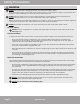
Safety Precautions WARNING DO NOT use a socket that is damaged or loose, as it could cause electric shock. • If the unit makes strange or abnormal noises, emits an odor, or smoke begins to appear, stop operation and unplug the unit immediately. It could cause electric shock and/or fire. DO NOT allow the power cord to be near heating appliances, or flammable gas and combustibles (ex: gasoline, benzene, thinner, etc.), as these could cause a fire and/or explosion.
Safety Precautions CAUTION DO NOT touch the metal parts of the unit while the air filter is removed or personal injury could occur. DO NOT allow pets or house plants to be exposed to direct airflow from the unit, it could cause harm or injury. DO NOT use in a room that is not well ventilated, especially when used in a room with a stove as this could cause an oxygen shortage. DO NOT use strong detergent, such as wax or thinner, to clean the unit.
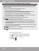
Safety Precautions WARNING REGARDING CURRENT DETECTION DEVICE The power cord of this air conditioner contains a current detection device that is designed to reduce the risk of fire by sensing if there is damage to the cord. In the event that the power supply cord is damaged, it cannot be repaired and it must be replaced with a cord from the product manufacturer. In order to test this function and the cord, follow these steps: 1.) Plug the air conditioner into the wall outlet. 2.
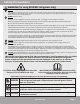
Safety Precautions WARNING (for using R290/R32 refrigerant only) DO NOT use any other methods to clean or defrost the unit than those recommended by the manufacturer. • The appliance should be stored in a room that does not contain continuously operating ignition sources (ex: open flames, an operating electric heater, or an operating gas appliance), and ignition sources (ex: an operating electric heater) close to the appliance. DO NOT Pierce or burn.
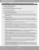
Safety Precautions WARNING (for using R290/R32 refrigerant only, continued) 1. Transport of equipment containing flammable refrigerants Refer to transport regulations. 2. Marking of equipment using signs Refer to local regulations. 3. Disposal of equipment using flammable refrigerants Refer to national regulations. 4. Storage of equipment/appliances The storage of equipment should be in accordance with the manufacturer’s instructions. 5.
Safety Precautions WARNING (for using R290/R32 refrigerant only, continued) • The amount of charge is in accordance with the size of the room which the refrigerant containing parts are installed. • The ventilation machinery and outlets are operating sufficiently and are not obstructed. • If an indirect refrigerant circuit is being used, the secondary circuit needs to be checked for the presence of refrigerant. • Markings and signs on the unit are still visible and legible.
Safety Precautions WARNING (for using R290/R32 refrigerant only, continued) 8. Repair to Intrinsically Safe Components DO NOT apply any permanent inductive or capacitance loads to the circuit without ensuring that the permissable voltage current permitted for the equipment in use will not be exceeded. Intrinsically safe components are the only types of components that can have worked performed on them while live and in the presence of a flammable atmosphere.
Safety Precautions WARNING (for using R290/R32 refrigerant only, continued) Flushing should be achieved by breaking the vacuum in the system with OFN and continuing to fill until working pressure is achieved. Then, vent it into the atmosphere, before finally pulling down to a vacuum. This process should be repeated until no refrigerant is present in the system. When the final OFN charge is used, the system should be vented down until reaches atmospheric pressure to enable work to be performed.
Safety Precautions WARNING (for using R290/R32 refrigerant only, continued) 10.) Once the cylinders have been filled correctly and the process has been completed, ensure that the cylinders and equipment are removed from the site promptly, and all isolation valves on the equipment are closed off. 11.) The recovered refrigerant should not be charged into another refrigeration system until it has been cleaned and checked. 15.
Installation Summary Installation Instructions 1 Installation Hardware Type B 1/2” Screw 2* Window Sash Lock 1 Type B 1/4” Screw Type A 1/2” Screw 2* Additional Side Arm Foam Window Sealing Foam 2 1 Bracket Sealing Foam 1 Type A 1” Screw 3* 2* Main Bracket 1 Side Arm Foam 2 1 Window Sash Foam 1 Right Extension Arm (For 26”-36” windows) Right Extension Arm - Short (For 22”-26” windows) 1 Main Support Pin 2* Cotter Pin 2* Open Window Bracket – LH 1 Open Window Bracket – RH 1 *D
Installation Instructions WINDOW REQUIREMENTS BEFORE YOU BEGIN Read these instructions completely and carefully. • • • • • • • • • IMPORTANT- Save these instructions for local inspector’s use. IMPORTANT- Ensure installation follows all local and state codes and ordinances. Note to Installer- Be sure to leave these instructions with the consumer. Note to consumer- Keep these instructions for future reference. Skill level- Installation of this appliance requires basic mechanical skills.
Installation Instructions Rear Cross Brace Main Support Right Extension Arm Spring Push Pin Left Extension Arm Horizontal Bracket Angled Support Arms Fig. 1 2 PREPARE THE MOUNTING BRACKET A. Remove the air conditioner, bracket, and hardware components from the carton and lay them on a flat surface. Adjust Center Adjust Fig. 2 B. Press spring-loaded push pin of the Left Extension Arm located on the Horizontal Bracket and adjust the arm outward.
Installation Instructions D. Now, you will apply the supplied Bracket Sealing Foam strips to the bottom of the bracket as depicted in Fig. 3. Apply Bracket Sealing Foam Apply Bracket Sealing Foam Apply Bracket Sealing Foam Bottom View Bracket Sealing Bracket SealingFoam Foam Fig. 3 3 INSTALL SUPPORT BRACKET A. Install the Main Support Bracket into the window opening. Ensure that the Horizontal Bracket and the Left and Right Extension Arms are located on the indoor side of the window.
Installation Instructions For Vinyl Type Windows with a Lipped Seal A2. Secure the bracket to the windowsill by drilling 1/8 in (3.175 mm) pilot holes through the holes of the vertical portion of the bracket and into the windowsill, refer to the arrows in the image below. Then, install the supplied Type A 1/2” screws (12.7 mm) into the vertical portion of the bracket and windowsill, as shown in Fig. 6 below. Use Type A 1/2” Screw Use Type A 1/2” Screw Fig. 6 For Wooden Type Windows with a Flat Seal A3.
Installation Instructions C. Once the bracket has been adjusted to desired level, insert the Main Support Pin through the holes of the Main Support and Angled Support Arm. Using the numbers on the Main Support, repeat the adjustment for the other Angled Support Arm (matching the hole and number from first support arm). Please refer to Fig. 9. Fig. 9 NOTE: If further adjustment is needed, use the alternate holes where the Main Supports attach to the Horizontal Bracket. D.
Installation Instructions 4 INSTALL AIR CONDITIONER TO BRACKET IMPORTANT Before proceeding to the next step, measure the width of your window track (the vertical track your window slides up and down in) before installing your air conditioner. If it is 1/2 in (12.7 mm) or less, flip the Anti-Tip Bracket so the small end faces out, then continue with the installation. Refer to the image to the right. WARNING DO NOT leave the unit unattended during the installation This side faces indoors A.
Installation Instructions C. Next, you must install the Open Window Brackets on each side of the unit. Use the Type B 1/4” screws (6.35 mm) for the portion of the bracket that attaches to the Horizontal Bracket and the Type B 1/2” screws (12.7 mm) for the portion of the bracket that attaches to the unit itself. Please refer to Fig. 16. WARNING Failure to install the Open Window Brackets could cause injury or property damage. Fig.
Installation Instructions B. In this step, depending on the type of window the unit is being installed in (vinyl or wooden), you will apply Window Sealing Foam to the Side Arm Foam as shown Fig.18 & Fig. 19. Please note that the Window Sealing Foam attaches to the side next to the air conditioner. Vinyl Type Windows with Lipped Sill Air Conditioner Side Wooden Type Windows with Flat Sill Air Conditioner Side Side Arm Foam Side Arm Foam Additional Side Arm Foam Window Sealing Foam Fig.
Installation Instructions D. The Anti-Tip Brackets must be extended into the window track opening (the vertical track your window slides up and down in) until it stops and sits against the face of the window track. In order to make this adjustment you must remove the factory-installed 1/2” Phillips head screw from each bracket. Once the adjustments have been made, secure the brackets in place by reinstalling the screws you originally removed. Please refer to the images below.
Installation Instructions E. Install a strip of Window Sealing Foam to the bottom of the lower portion of the window sash (bottom of the window that will lower into the slot of the air conditioner), sealing any small gaps between the window and air conditioner. Then, close the window and check for gaps. Fill any with included foam as needed. F. Extend the Integrated Window Locks (located in the U channel) until they contact the window. Please refer to Fig. 24.
Installation Instructions I. Finally, review the installation and check for any gaps or openings to the outside air. If any are found, cover them with the provided foam ensuring no outdoor air will leak inside. Any leaks that are not sealed could affect the performance of the air conditioner. Please refer to Fig. 27 for the areas to check for leaks/gaps. Check for Gaps Check for Gaps Fig.
2 Sounds During Normal Operation The following illustration and descriptions represent noises that may be heard from the air conditioner during normal operation. These are normal and do not indicate there is a malfunction. If you should hear noises other than the ones listed, or find the unit is funtioning abnormally, discontinue use, and refer to the troubleshooting section of this manual before contacting technical support.
Air Conditioner Operation & Features 3 Air Directional Louvers WARNING To reduce the risk of fire, electric shock, or personal injury read the IMPORTANT SAFETY INSTRUCTIONS before operating this appliance. Use SWING button for up/down direction CAUTION Always wait at least 3 minutes when turning the unit off then back on again. Also do this when changing from the COOL setting to the FAN setting and then back to the COOL setting.
Air Conditioner Operation & Features ELECTRONIC CONTROL OPERATING INSTRUCTIONS NOTE: Different models have different control buttons and indicator lights. Not all of the control buttons and indicator lights described below are available on your unit. Please check the control panel of the unit you purchased. The unit can be controlled by the controls on ther unit or with the remote. 2 3 4 5 6 7 8 9 1 Operation & Function of buttons 1 ON/OFF: Press ON/OFF button to turn the unit on or off.
Air Conditioner Operation & Features 4 ECO button Press ECO button to initiate this function. This function is available on the COOL, DRY, AUTO (only AUTO-COOLING and AUTO-FAN) modes. The fan will continue to run for 3 minutes after the compressor shuts off. The fan then cycles on for 2 minutes, at 10 minute intervals, until the room temperature is above the set temperature, at which time the compressor turns back on and cooling restarts.
Air Conditioner Operation & Features 8 SLEEP button Pressing the SLEEP button will initiate the sleep mode. In this mode, the selected temperature will increase by 2°F from the set temperature 30 minutes after the mode is selected. The temperature will then increase by another 2°F after an additional 30 minutes (total of 4°F). This new temperature will be maintained for 7 hours before it automatically returns to the originally selected temperature.
Refrigerant Piping Connection Care & Cleaning Cabinet Cleaning CAUTION Be sure to turn off the unit and unplug it from the outlet before cleaning to prevent electric shock or fire hazards. Clean the unit occasionally to keep it looking new. Air Filter Cleaning 4 Be sure to unplug the air conditioner before cleaning the cabinet in order to prevent electric shock or fire hazard.
Refrigerant Piping Connection Troubleshooting Tips 5 If your unit is not functioning or operating abnormally, please consult this list of common issues and solutions before contacting technical support. These could save you both time and money. Problem Solution Power cord plug could be disconnected. Push plug firmly into outlet. Air conditioner does not start A fuse could be could be blown or the circuit breaker could be tripped. Replace fuse with a time delay fuse or reset the circuit breaker.
Troubleshooting Tips Problem Solution Water dripping Improper installation. Tilt air conditioner slightly to the outside to allow water INSIDE when unit drainage. Refer to installation instructions - check with installer. is cooling. Water dripping OUTSIDE when unit is cooling. Unit is removing large quantities of moisture from humid room. This is normal during excessively humid days. Remote Sensing Deactivating Prematurely (some models) Remote control not located within operating range.
U-Shaped Window Unit Air Conditioner Model: MWUC**5 The design and specifications of this product and/or manual are subject to change without prior notice. Consult with the sales agency or manufacturer for details.