PIP-MS 1-5KVA (800W-4KW) INVERTER / CHARGER User Manual *with built-in 60amp MPPT SCC
Table Of Contents ABOUT THIS MANUAL ..................................................................................................................................... 1 Purpose ............................................................................................................................................................ 1 Scope ...............................................................................................................................................................
ABOUT THIS MANUAL Purpose This manual describes the assembly, installation, operation and troubleshooting of this unit. Please read this manual carefully before installations and operations. Keep this manual for future reference. Scope This manual provides safety and installation guidelines as well as information on tools and wiring. SAFETY INSTRUCTIONS WARNING: This chapter contains important safety and operating instructions. Read and keep this manual for future reference. 1.
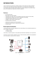
INTRODUCTION This is a multi-function inverter/charger, combining functions of inverter, MPPT solar charger and battery charger to offer uninterruptible power support with portable size. Its comprehensive LCD display offers user-configurable and easy-accessible button operation such as battery charging current, AC/solar charger priority, and acceptable input voltage based on different applications.
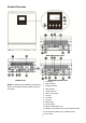
Product Overview 4KVA/5KVA single model 1-3KVA model NOTE: For parallel model installation and operation, please check separate parallel installation guide for the details. 4KVA/5KVA parallel model 1. LCD display 2. Status indicator 3. Charging indicator 4. Fault indicator 5. Function buttons 6. Power on/off switch 7. AC input 8. AC output 9. PV input 10. Battery input 11. Circuit breaker 12. RS232 communication port 13. Parallel communication cable (only for parallel model) 14.
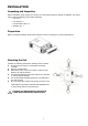
INSTALLATION Unpacking and Inspection Before installation, please inspect the unit. Be sure that nothing inside the package is damaged. You should have received the following items inside of package: The unit x 1 User manual x 1 Communication cable x 1 Software CD x 1 Preparation Before connecting all wirings, please take off bottom cover by removing two screws as shown below.
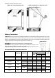
Install the unit by screwing three screws. 1-3KVA 24V, 1KVA/3KVA 48V model 2-3KVA 24V/48V Plus, 4-5KVA 48V model Battery Connection CAUTION: For safety operation and regulation compliance, it’s requested to install a separate DC over-current protector or disconnect device between battery and inverter. It may not be requested to have a disconnect device in some applications, however, it’s still requested to have over-current protection installed.
Please follow below steps to implement battery connection: 1. Assemble battery ring terminal based on recommended battery cable and terminal size. 2. Connect all battery packs as units requires. It’s suggested to connect at least 100Ah capacity battery for 1-3KVA model and at least 200Ah capacity battery for 4KVA/5KVA model. NOTE: Please only use sealed lead acid battery or sealed GEL/AGM lead-acid battery. 3.
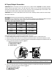
AC Input/Output Connection CAUTION!! Before connecting to AC input power source, please install a separate AC breaker between inverter and AC input power source. This will ensure the inverter can be securely disconnected during maintenance and fully protected from over current of AC input. The recommended spec of AC breaker is 10A for 1KVA, 20A for 2KVA, 32A for 3KVA, 40A for 4KVA and 50A for 5KVA. CAUTION!! There are two terminal blocks with “IN” and “OUT” markings.
5. Make sure the wires are securely connected. CAUTION: Important Be sure to connect AC wires with correct polarity. If L and N wires are connected reversely, it may cause utility short-circuited when these inverters are worked in parallel operation. CAUTION: Appliances such as air conditioner are required at least 2~3 minutes to restart because it’s required to have enough time to balance refrigerant gas inside of circuits.
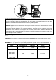
PV Module Selection: When selecting proper PV modules, please be sure to consider below parameters: 1. Open circuit Voltage (Voc) of PV modules not exceeds max. PV array open circuit voltage of inverter. 2. Open circuit Voltage (Voc) of PV modules should be higher than min. battery voltage. Solar Charging Mode 1KVA 24V INVERTER MODEL 1KVA 48V 2KVA 24V 3KVA 48V 3KVA 24V 2KVA 24V 2KVA 48V Plus/ 3KVA Plus/3KVA 48V 24V Plus Plus/ 4KVA/5KVA Max.
Communication Connection Please use supplied communication cable to connect to inverter and PC. Insert bundled CD into a computer and follow on-screen instruction to install the monitoring software. For the detailed software operation, please check user manual of software inside of CD. Dry Contact Signal There is one dry contact (3A/250VAC) available on the rear panel. It could be used to deliver signal to external device when battery voltage reaches warning level.
OPERATION Power ON/OFF Once the unit has been properly installed and the batteries are connected well, simply press On/Off switch (located on the button of the case) to turn on the unit. Operation and Display Panel The operation and display panel, shown in below chart, is on the front panel of the inverter. It includes three indicators, four function keys and a LCD display, indicating the operating status and input/output power information.
LCD Display Icons Icon Function description Input Source Information Indicates the AC input. Indicates the PV input Indicate input voltage, input frequency, PV voltage, battery voltage and charger current. Configuration Program and Fault Information Indicates the setting programs. Indicates the warning and fault codes. Warning: Fault: flashing with warning code.
In battery mode, it will present battery capacity. Load Percentage Battery Voltage LCD Display < 1.717V/cell 1.717V/cell ~ 1.8V/cell Load >50% 1.8 ~ 1.883V/cell > 1.883 V/cell < 1.817V/cell 1.817V/cell ~ 1.9V/cell 50%> Load > 20% 1.9 ~ 1.983V/cell > 1.983 < 1.867V/cell 1.867V/cell ~ 1.95V/cell Load < 20% 1.95 ~ 2.033V/cell > 2.033 Load Information Indicates overload. Indicates the load level by 0-24%, 25-50%, 50-74% and 75-100%.
LCD Setting After pressing and holding ENTER button for 3 seconds, the unit will enter setting mode. Press “UP” or “DOWN” button to select setting programs. And then, press “ENTER” button to confirm the selection or ESC button to exit. Setting Programs: Program Description Selectable option Escape 00 Exit setting mode Solar energy provides power to the loads as first priority.
10A (Not available for 2-3KVA 24V Plus) 20A 30A 40A 50A 60A (default) Available options in 4K/5K model 70A 80A 90A 100A 110A 120A Appliances (default) If selected, acceptable AC input voltage range will be within 03 AC input voltage range 90-280VAC. UPS If selected, acceptable AC input voltage range will be within 170-280VAC. Saving mode disable If disabled, no matter connected load (default) is low or high, the on/off status of inverter output will not be effected.
Restart disable Restart enable 07 Auto restart when over temperature occurs (default) 110V 120V (default) 08 Output voltage (only available for 120Vac models) 50Hz (default) 60Hz 09 Output frequency Available options in 1KVA 24V and 2KVA 24V Plus 120Vac model: 10A 20A(default): Available options in 2-3KVA 24V and 2-3KVA 24V Plus models: 20A 30A (default) Available options in 1KVA/3KVA 48V and 2-3KVA 48V Plus models: 10A 11 Maximum utility charging current 15A(default): Available options
Available options in 24V models: 12 Setting voltage point back to utility source when selecting “SBU priority” or “Solar first” in program 01. 22.0V 22.5V 23.0V (default) 23.5V 24.0V 24.5V 25.0V 25.5V Available options in 48V models: 44V 45V 46V (default) 47V 48V 49V 50V 51V Available options in 24V models: 13 Setting voltage point back to battery mode when selecting “SBU priority” or “Solar first” in program 01. Battery fully charged 24V 24.5V 25V 25.
26.5V 27V (default) 27.5V 28V 28.5V 29V Available options in 48V models: Battery fully charged 48V 49V 50V 51V 52V 53V 54V (default) 55V 56V 57V 58V If this inverter/charger is working in Line, Standby or Fault mode, charger source can be programmed as below: Solar first first priority. Charger source priority: 16 Utility will charge battery only when To configure charger source priority Solar energy will charge battery as solar energy is not available.
Solar and Utility (Only available for 4KVA/5KVA model) Only Solar Solar energy and utility will charge battery at the same time. Solar energy will be the only charger source no matter utility is available or not. If this inverter/charger is working in Battery mode or Power saving mode, only solar energy can charge battery. Solar energy will charge battery if it's available and sufficient.
If self-defined is selected in program 5, this program can be set up. Setting range is from 24.0V to 29.2V for 24V model and 48.0V to 58.4V for 48V model. Increment of each click is 0.1V. 24V model default to 27.0V 48V model default setting: 54.0V 27 Floating charging voltage If self-defined is selected in program 5, this program can be set up. Setting range is from 24.0V to 29.2V for 24V model, 48.0V to 58.4V for 48V model. Increment of each click is 0.1V. 24V model default setting: 21.
Display Setting The LCD display information will be switched in turns by pressing “UP” or “DOWN” key. The selectable information is switched as below order: input voltage, input frequency, PV voltage, MPPT charging current, MPPT charging power, battery voltage, output voltage, output frequency, load percentage, load in VA, load in Watt, DC discharging current, main CPU Version and second CPU Version.
Battery voltage=25.5V, discharging current=1A Battery voltage/ DC discharging current Output frequency=50Hz Output frequency Load percent=70% Load percentage When connected load is lower than 1kVA, load in VA will present xxxVA like below chart. Load in VA When load is larger than 1kVA (≧1KVA), load in VA will present x.xkVA like below chart.
When load is lower than 1kW, load in W will present xxxW like below chart. Load in Watt When load is larger than 1kW (≧1KW), load in W will present x.xkW like below chart. Main CPU version 00014.04 Main CPU version checking Secondary CPU version 00003.
Operating Mode Description Operation mode Description LCD display Charging by utility. Standby mode / Power saving mode Note: *Standby mode: The inverter is not turned on yet but at this No output is supplied by the time, the inverter can charge unit but it still can charge battery without AC output. batteries. Charging by PV energy. *Power saving mode: If enabled, the output of inverter No charging. will be off when connected load is pretty low or not detected. Charging by utility.
Power from battery and PV energy. The unit will provide output Battery Mode power from battery and PV power. Power from battery only. Fault Reference Code Fault Code Fault Event 01 Fan is locked when inverter is off. 02 Over temperature 03 Battery voltage is too high 04 Battery voltage is too low 05 06 Icon on Output short circuited or over temperature is detected by internal converter components. Output voltage is abnormal. (For 1K/2K/3K model) Output voltage is too high.
Warning Indicator Warning Code Warning Event Audible Alarm 01 Fan is locked when inverter is on. Beep three times every second 03 Battery is over-charged Beep once every second 04 Low battery Beep once every second 07 Overload Beep once every 0.5 second 10 Output power derating Beep twice every 3 seconds 12 13 14 Solar charger stops due to low battery. Solar charger stops due to high PV voltage. Solar charger stops due to overload.
SPECIFICATIONS Table 1 Line Mode Specifications 1KVA 24V 2KVA 24V INVERTER MODEL 3KVA 24V 1KVA 48V 3KVA 48V Input Voltage Waveform 2KVA 24V Plus 3KVA 24V Plus 4KVA 2KVA 48V Plus 5KVA 3KVA 48V Plus Sinusoidal (utility or generator) Nominal Input Voltage 120Vac or 230Vac 95Vac±7V or 170Vac±7V (UPS) Low Loss Voltage 65Vac±7V or 90Vac±7V (Appliances) 100Vac±7V or 180Vac±7V (UPS); Low Loss Return Voltage 70Vac±7V or 100Vac±7V (Appliances) High Loss Voltage 140Vac±7V or 280Vac±7V High Loss Return
Table 2 Inverter Mode Specifications 1KVA 24V 1KVA 48V 2KVA 24V INVERTER MODEL 3KVA 24V 2KVA 24V Plus 4KVA 2KVA 48V Plus 5KVA 3KVA 48V Plus 3KVA 24V Plus Rated Output Power 3KVA 48V 1KVA/0.8KW 2KVA/1.6KW 3KVA/2.4KW 1KVA/1KW 2KVA/1.6KW 3KVA/2.4KW 4KVA/3.
Table 3 Charge Mode Specifications Utility Charging Mode 1KVA 24V INVERTER MODEL 2KVA 24V Plus 120Vac Charging Current (UPS) @ Nominal Input Voltage Bulk Charging Voltage 2KVA 24V 1KVA 48V 3KVA 24V 2KVA 48V 3KVA 48V 4KVA 2KVA 24V Plus Plus 120Vac 2KVA 48V Plus 3KVA 24V Plus 3KVA 48V Plus 5KVA 2/10A/ 10/20A Flooded Battery AGM / Gel Battery Floating Charging Voltage 20/30A 5/10A 10/15A 20/30A/ 40/50/60A 29.2 58.4 28.2 56.
Joint Utility and Solar Charging (Only available for 4KVA and 5KVA model) Max Charging Current 120Amp Default Charging Current 60Amp Table 4 General Specifications 2KVA 24V Plus INVERTER MODEL 1KVA 24V 1KVA 48V 2KVA 24V 3KVA 24V 3KVA 24V Plus 3KVA 48V 2KVA 48V Plus 4KVA 5KVA 3KVA 48V Plus Safety Certification CE Operating Temperature 0°C to 55°C Range Storage temperature -15°C~ 60°C Dimension (D*W*H), mm Net Weight, kg 128 x 272 x 355 7.4 7.6 30 140 x 295 x 479 8.0 11.
TROUBLE SHOOTING Problem Unit shuts down automatically during startup process. No response after power on. Mains exist but the unit works in battery mode. When the unit is turned on, internal relay is switched on and off repeatedly. LCD/LED/Buzzer Explanation / Possible cause LCD/LEDs and buzzer will be active for 3 seconds and then complete off. The battery voltage is too low (<1.91V/Cell) 1. Re-charge battery. 2. Replace battery. No indication. 1. The battery voltage is far too low. (<1.
Appendix: Approximate Back-up Time Table Model 1KVA 2KVA 3KVA Model 1KVA Load (VA) Backup Time @24Vdc 100Ah (min) Backup Time @24Vdc 200Ah (min) 200 766 1610 400 335 766 600 198 503 800 139 339 1000 112 269 200 766 1610 400 335 766 600 198 503 800 139 339 1000 112 269 1200 95 227 1400 81 176 1600 62 140 1800 55 125 2000 50 112 300 449 1100 600 222 525 900 124 303 1200 95 227 1500 68 164 1800 56 126 2100 48 108 2400 35 94 2700 31
Model 2KVA 3KVA 4KVA 5KVA Load (VA) Backup Time @ 48Vdc 100Ah (min) Backup Time @ 48Vdc 200Ah (min) 200 1581 3161 400 751 1581 600 491 1054 800 331 760 1000 268 615 1200 221 508 1400 172 387 1600 136 335 1800 120 295 2000 106 257 300 1054 2107 600 491 1054 900 291 668 1200 196 497 1500 159 402 1800 123 301 2100 105 253 2400 91 219 2700 71 174 3000 63 155 400 766 1610 800 335 766 1200 198 503 1600 139 339 2000 112 269 2400 95