7 ( & + 1 , & $ / )&; , 1 6 7 5 8 & 7 , 2 1 6 T30.30306.
7$%/( 2) &217(176 , ,1752'8&7,21 1 2 3 4 5 - ,, ,167$//$7,21 1 2 3 4 5 6 7 - PRODUCT DESCRIPTION....................................................................................................................
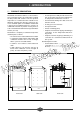
, ,1752'8&7,21 352'8&7 '(6&5,37,21 • A control panel assembly and all electrical controls for operation of the boiler, including a water temperature thermometer in circuit 1 Model FCX oil fired boiler utilizes a sealed combustion system that operates at a temperature at which the flue products will condense. The flue products temperature is so low that the unit is suitable for use with PVC / Polypropylene flue pipes, which are offered as standard options for installation.
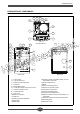
,1752'8&7,21 '(6,*1$7,21 2) &20321(176 21 20 19 18 17 22 14 3 24 1 2 1 16 2 View from above 26 17 18 19 21 22 25 3 15 4 14 7 5 23 13 20 6 12 8 8 9 11 10 Front view &RQWURO 3DQHO &RQWURO 3DQHO &RYHU 6DIHW\ 3UHVVXUH 5HOLHI 9DOYH &RQGHQVHU 0DQXDO 0L[LQJ 9DOYH &RPEXVWLRQ 3URGXFW 3UHVVXUH 7HVW 3RLQW &RQGHQVHU ,QVSHFWLRQ 3RUW &RQGHQVDWH 'UDLQ 'UDLQ &RFN %XUQHU $LU ,QOHW 3LSH 2LO %XUQHU 6DIHW\ /LJKW DQG 5HVHW %XWWRQ 6LJKW *ODVV %RLOHU 6KHOO
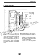
,1752'8&7,21 %2,/(5 23(5$7,21 Circuit heating return or 2nd circuit heating output 1st circuit heating output Water is circulated through the boiler heat exchanger and condenser circuits where it is heated by the combustion of the oil burner. Two independent water-heating circuits can be connected to the unit: Combustion air is drawn into the oil burner by the burner fan through the air intake hose connected to the coaxial flue/combustion air intake separator tube assembly.
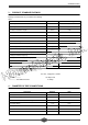
,1752'8&7,21 352'8&7 67$1'$5' 5$7,1*6 Ratings for Model FCX are provided in the following table: 3HUIRUPDQFH 3DUDPHWHU 8QLWV 3URGXFW 5DWLQJ Rated Output BTUH 76,000 Rated Input BTUH 81,250 Combustion Chamber Length Inches 8.98 Combustion Chamber Diameter Inches 11.5 Combustion Chamber Volume Cu. Inches 915 Combustion Prod. Circuit Volume Cu. Inches 3051 Flue Pressure Drop Inches H2O 0.10 Psig 43.5 Max Heating circuit water temperature Deg.
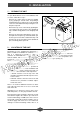
,, ,167$//$7,21 23(1,1* 7+( 81,7 To open Model FCX to access for installation, and/ or service, follow these steps : - Remove the control panel escutcheon molding (2) by grasping it on both sides and pulling it outward towards you and up. The escutcheon will come free of the attachment clips leaving the control panel exposed. - Remove the top cover of the unit (A) by lifting the cover at the front and rear to free the attachment clips, and then simply lift the cover straight up and off.
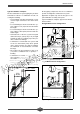
,167$//$7,21 )/8( &211(&7,216 $1' 5287,1* 3RO\SURS\OHQH 39& &RQFHQWULF 7HUPLQDO )RU )ODW RU 6ORSLQJ 5RRI Connection of the coaxial flue/combustion air piping system is in the back of the unit to the separator tube assembly. The combustion products are vented from the boiler and condenser through the center of the coaxial tube, while the combustion air is supplied through the outside ring of the coaxial tube.
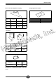
,167$//$7,21 3RO\SURS\OHQH 5RRI 3ODWH 6OHHYH 7LOH ZLWK $GDSWDEOH &RXSOLQJ 5HIHUHQFH 6ORSH &RYHULQJ W\SH &RORU 5HIHUHQFH &RORU N40.12165 25 - 45 deg Tile Tile A90.12172 Black N40.12166 35 - 55 deg Tile Tile N40.12167 35 - 55 deg Slate Shingle Black 3RO\SURS\OHQH 39& &RQFHQWULF (OERZ - joint fitting - 45 ° bend 90 ° bend 5HIHUHQFH &RORU , ' 2 ' N40.28395 45 deg 3.15 inch (80mm) 4.92 inch (125mm) N40.28396 90 deg 3.15 inch (80mm) 4.
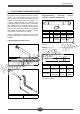
,167$//$7,21 7\SLFDO LQVWDOODWLRQ H[DPSOHV All flue-piping components must be assembled to provide an airtight flue/ combustion air system. The flue/combustion air system piping may be either horizontal or vertical or a combination of both, observing the following: Application of liquid soap over the flue pipes to be joined will aid in assembly of the parts. • The maximum unrestricted horizontal or vertical flue length shall not be more than 16.4 ft (5 m).
,167$//$7,21 7\SLFDO LQVWDOODWLRQ H[DPSOHV FRQW / / / / / / Options: - 1 90 deg concentric elbow - 3 Concentric extensions - 2 45 deg concentric elbows - 1 concentric vertical terminal - 1 sleeve tile roof flange - 1 roof plate Options: - 1 90 deg concentric elbow - Concentric extensions - 1 concentric vertical terminal - 1 sleeve tile roof flange - 1 roof plate PD[ / / IW P / IW P / IW P ≤ IW P PD[ / / IW P ≤ IW P
,167$//$7,21 7\SLFDO LQVWDOODWLRQ H[DPSOHV FRQW 90° elbow 90° elbow 45° elbow 45° elbow View from above View from above rear boiler rear boiler / / / / Options: - 1 90 deg concentric elbow - 3 Concentric extensions - 3 45 deg concentric elbows - 1 concentric vertical terminal - 1 sleeve tile roof flange - 1 roof plate Options: - 1 45 deg concentric elbow - 1 90 deg concentric elbow - Concentric extensions - 1 concentric vertical terminal - 1 sleeve tile roof flange - 1 roof plate PD[
,167$//$7,21 7\SLFDO LQVWDOODWLRQ H[DPSOHV FRQW 90° elbow 45° elbow view from above rear boiler 1,80 m 5.9 ft 1 in Options: - 1 45 deg concentric elbow - 2 90 deg concentric elbow - 1 concentric extension - 1 straight horizontal flue kit &21'(16$7( '5$,1 &211(&7,21 Connection of the condensate drain piping system is to the back of the unit beneath the flue/combustion air separator tube assembly. The condensate drain tube provided in the unit is 1 - 19/32 inches (40 mm) O.D.
,167$//$7,21 :$7(5 &,5&8,7 &211(&7,216 • Isolation valves may be used in the various circuits to facilitate boiler maintenance without having to completely drain each circuit. NEVER place an isolation valve between a pressure relief device and a water tank. Water circuit connections are made in the back of the unit utilizing the four 1" male pipe thread couplings provided.
,167$//$7,21 Various typical water circuits (cont) &RQQHFWLRQ WR D GRXEOH KHDWLQJ FLUFXLW & 0 Rc1 & Rc2 VM1 M P2 Dc2 Dc1 & Sd VM2 C %RLOHU 3UHVVXUH JDXJH & 5DGLDWRU FLUFXLW 90 VW FLUFXLW PL[HU YDOYH 'F VW FLUFXLW KHDWLQJ RXWSXW 5F VW FLUFXLW KHDWLQJ UHWXUQ & 3 90 'F 5F 6G 8QGHUIORRU KHDWLQJ FLUFXLW QG FLUFXLW KHDWLQJ FLUFXODWRU QG FLUFXLW PL[HU YDOYH QG FLUFXLW KHDWLQJ RXWSXW QG FLUFXLW KHDWLQJ UHWXUQ +HDWLQJ RXWSXW VHQVRU &RQQHFWLRQ WR D GRXEOH KHDWLQJ FLUFXLW ZLWK D GR
,167$//$7,21 (/(&75,&$/ &211(&7,216 :$51,1* (/(&75,&$/ 6+2&. +$=$5' ',6&211(&7 7+( 32:(5 6833/< %()25( $77(037,1* (/(&75,&$/ ,167$//$7,21 2) 7+( 81,7 down caused by an unrelated electrical circuit fault, the unit and any related electrical components should be connected to a separate branch circuit specifically dedicated for that purpose. Electrical power and control connections are made to pigtail leads that exit through a hole in the right rear of the unit (facing the front of the unit).
,167$//$7,21 Route the factory supplied main power pigtail leads through the connector from inside the unit and secure the connector clamp on the wires. The hole in the right rear of the unit is a large flat oval. Mount a Listed 2 x 4 inch, "HandiBox" type junction box over the oval hole in such manner that part of the hole is left open. When installing the junction box, center the box vertically over the oval hole by using the center knockout in the box.
,,, 67$57 83 $1' 23(5$7,21 35( 67$57 ),1$/ 6<67(0 &+(&. freeze solution if appropriate. Open any shutoff valves in the system. Before starting normal operation of the boiler and heating system, perform the following final installation procedures: • Fill the condensate drain trap with water. • Leak-check the flue/combustion air system to minimize the likelihood of leakage. • Leak-check the fuel oil supply system and open any fuel shut-off valves.
67$57 83 $1' 23(5$7,21 $'-867,1* 7+( 2,/ %851(5 While the oil burner is adjusted at the factory, it is recommended that the operating characteristics of the burner be determined at start-up and readjusted if necessary. Run the unit long enough at the burner maximum firing rate to make sure the burner has reached a stable maximum operating temperature. THEN, check the burner and adjust as follows: 7 Check to determine that the smoke spot number does not exceed 0.5 with a Bacharach control.
,9 0$,17(1$1&( It is recommend that the boiler and flue/combustion air system be inspected and maintained annually by a qualified technician. ',6&211(&7 $// (/(&75,&$/ &,5&8,76 %()25( 6(59,&,1* 7+( 81,7 &/26( $1< ,62/$7,21 9$/9(6 7+$7 0$< %( ,1 7+( :$7(5 6<67(0 6+87 2)) 7+( )8(/ 2,/ 6833/< ,) 6(59,&,1* 7+( %851(5 plate by removing the screws in the rear and lifting. Remove the control panel cover screws and remove the control panel cover.
0$,17(1$1&( %851(5 0$,17(1$1&( if necessary. Cleaning and adjustment is always appropriate during periodic inspection. Once adjusted properly, regular maintenance of the oil burner is not generally required. A routine examination of the burner should include examination of the burner fan and nozzle for dirt and the spark electrodes for proper clearances. Replace the fuel filter If burner firing rate adjustment is required, follow instructions in "Adjusting the Oil Burner". $/:$<6 &+(&.
0$,17(1$1&( &+$1*,1* $ 7+(50267$7 25 7+( 7+(5020(7(5 remove the thermostat. Replace the thermostat with another, routing the bulb capillary the same way as the original, replacing the bulb properly into the pocket as far as possible. Replacement of the thermostats or the thermometer requires removal of the bulb from its location and the control from the control box. • The bulb for the Boiler Temperature Thermometer is located on the first circuit heating output tube.
9 23(5$7,1* )$8/76 During the course of seemingly normal operation, there may be operating faults experienced in the system. Some of the more common faults that may be encountered are: %851(5 )$8/7 6+87 '2:1 - The burner may shut down for any of several reasons, at which point the burner safety device light (red) on the control panel will be ON and the there will be a green fault indicator light lit on the oil burner.
SEPTEMBRE 2001 MPI - P.O.