
User`s guide

21
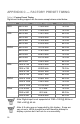
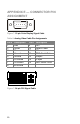
Table 8: Digital Video Cable Pin Assignments
Pin # Description Pin # Description
1 TMDS RX2- 13 Floating
2 TMDS RX2+ 14 +5V Power
3TMDS
Ground
15 Ground
4 Floating 16 Hot Plug Detect
5 Floating 17 TMDS RX0-
6 DDC Clock 18 TMDS RX0+
7 DDC Data 19 TMDS Ground
8 Floating 20 Floating
9 TMDS RX1- 21 Floating
10 TMDS RX1+ 22 TMDS Ground
11 TMDS
Ground
23 TMDS Clock+
12 Floating 24 TMDS Clock-
APPENDIX F — ACCEPTABLE LCD
DEFECTS
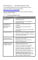
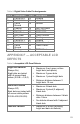
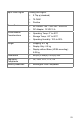
Table 9: Acceptable LCD Panel Defects
Bright Dot Failures
(Always On)
Bright dots are tested
with full screen black
pattern (R.G.B. = 0,0,0)
• Maximum 5 red, green or blue
bright dots (sub-pixels)
• Maximum 3 green dots
• Maximum 1 joined bright dots
• Minimum distance between 2
bright dots: 10 mm
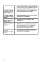
Black Dot Failures
(Always Off)
Black dots are tested with
full screen white pattern
(R.G.B.=255,255,255)
• Maximum 5 black dots
• Maximum 2 joined (2 adjacent)
black dots
• Minimum distance between 2 black
dots: 10mm
• No defects allowed with 3 adjacent
black dots
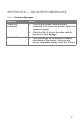
Total Dot Failures
• Maximum of 8 dots (including
bright and dark dot defects)