
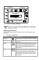
User`s guide

20
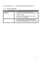
APPENDIX E — CONNECTOR PIN
ASSIGNMENT
15
6
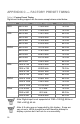
10
11 15
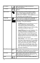
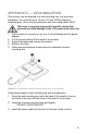
Figure 7: 15-pin Color Display Signal Cable
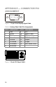
Table 6: Analog Video Cable Pin Assignments
Pin # Description Pin # Description
1 Red 9 +5V
2 Green 10 Detect Cable
3Blue 11NC
4 Ground 12 DDC-Serial Data
5 Ground 13 H-sync
6 R-Ground 14 V-sync
7 G-Ground 15 DDC-Serial Clock
8 B-Ground
Figure 7: 24-pin DVI Signal Cable