
User`s guide

14
WARRANTY INFORMATION
In the unlikely event that you have a failure with your MPC monitor, you
can contact MPC Technical Support at
http://support.buympc.com/index.html.
If you do not have Internet access, you may also call MPC Technical
Support at (800) 877-8856. Technical Support will provide you with
instructions for returning the failed monitor.
FEATURES
Energy Star Standards
This monitor may appear to be non-functional if there is no video input
signal. For this monitor to operate properly there must be a video-input
signal.
This monitor meets power management standards as set by the Video
Electronics Standards Association (VESA) and/or the United States
Environmental Protection Agency (EPA) and the Swedish Confederation
Employees (NUTEK). This feature is designed to conserve electrical
energy by reducing power consumption when there is no video input
signal present. When there is no video input signal, this monitor,
following a time-out period, will automatically switch to a low power
consumption mode. This reduces the monitor's internal power supply
consumption. After the video input signal is restored, full power is
restored, and the display is automatically redrawn. The appearance is
similar to a "Screen Saver" feature, except the display is completely off.
The display is restored by pressing a key on the keyboard or clicking the
mouse.
Plug & Play DDC1/2B Feature
This monitor is equipped with VESA DDC1/2B capabilities according to
the VESA DDC STANDARD. These capabilities allow the monitor to
inform the host system of its identity and, depending on the level of DDC
used, communicate additional information about its display capabilities.
The communication channel is defined in two levels: DDC1 and DDC2B.
The DDC1 is a uni-directional data channel from the display to the host
that continuously transmits EDID information. The DDC2B is a bi-
directional data channel based on the I²C protocol. The host can request
EDID information over the DDC2B channel.
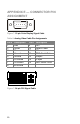
See “Appendix E — Connector Pin Assignment” on page 20 for
connector pin assignments.