F1925 LCD Monitor User’s Guide
Table of Contents User’s Guide........................................................................3 Packing List.........................................................................3 Safety Information ..............................................................3 LCD Monitor Features ........................................................5 Setup Instructions ..............................................................6 Monitor Base ...............................................................
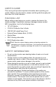
USER’S GUIDE This user’s guide provides important information about operating your monitor. Before using the monitor, please read this guide thoroughly and then save it for future reference. PACKING LIST Before setting up and using your monitor, examine the items in the monitor package. If anything is missing or damaged, please contact MPC immediately.
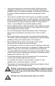
• The monitor must only be connected to the AC power source as indicated on the label. If you are unsure of the type of AC power available, ask your local power company. Only connect this monitor to a power outlet that matches the power requirements of this monitor. • The monitor is equipped with a three-prong, grounded plug (a plug with a third pin for grounding). For safety purposes, this plug will only fit into a grounded power outlet.
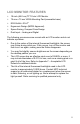
LCD MONITOR FEATURES • • • • • • 19-inch (48.0 cm) TFT Color LCD Monitor 75 mm x 75 mm VESA Mounting Pad (removable base) EPA ENERGY STAR® Ergonomic Design (MPRII Approved) Space Saving, Compact Case Design Dual Input – Analog and Digital The following occurrences are normal with an LCD monitor and do not indicate a problem. • Due to the nature of the internal fluorescent backlights, the screen may flicker during initial use.
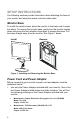
SETUP INSTRUCTIONS The following sections provide information about attaching the base to your monitor and using the power cord and video cable. Monitor Base To install the monitor base, place the monitor in the base until it snaps into place. To remove the monitor base, gently turn the monitor upside down and press the four retention clips apart to release the base. Pull the base straight away from the monitor. See Figure 1 below.
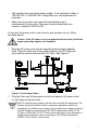
• This monitor has a universal power supply. It can operate in either a 100/120 VAC or 220/240 VAC voltage area (no user adjustment is required). • Make sure the power cord meets the specifications and requirements for your area. The power cord included with your monitor is rated for 100/120 VAC. To connect the power cord to your monitor and a power source, follow the steps below: Caution: If the AC outlet is not grounded (with three holes), install the proper grounding adapter (not supplied).
Video Cables The monitor comes with separate video cables for analog and digital connections. The cable you choose to use will depend on the input type you select. The analog cable has a blue 15 pin connector at each end. The digital cable has a white 24+ pin connector at each end. Caution: Do not bend the signal cable excessively, or you might break the wires inside the cable.
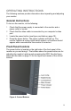
OPERATING INSTRUCTIONS The following sections provide information about operating and adjusting your monitor. General Instructions To turn on the monitor, do the following: 1 2 3 4 Check that the power supply is connected to the monitor and a power outlet or socket. Check that the video cable is connected to your computer’s video port. Locate the power button (see figure and table on page 10). Press the power button. The power indicator will light up.
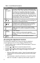
Table 1: Control Buttons Descriptions Feature 1 Auto Config/Exit Description The Auto Config button is used to automatically set the H-Pos, V-Pos, Clock, and Focus. Press and hold this button for 2 seconds to begin the auto config cycle. The Auto Configuration function is disabled when the digital input is selected. This adjustment is not necessary with a digital source. This also acts as the Exit button. Press it to close the OSD menu. This will also back out of a menu selection.
H:60KHz R V:75KHz Contrast G 70 B EXIT R C1 C2 Figure 5: On Screen Display (OSD) Menu Note: If you do not make any OSD menu adjustments or selections for more than 10 seconds, the current setup will be saved, and the OSD will disappear automatically. Adjusting the Picture The table below describes the functional control icons that appear on the OSD menu. Table 2: Functional Control Icons Function Contrast Icon Description Use this function to adjust the picture’s contrast.
H-Position Use this function to adjust the picture’s horizontal position. Use this function to adjust the picture’s vertical position. V-Position Input Select Use this function to select analog or digital input. When Digital is selected the following controls will be disabled: Clock, Phase, HPosition and V-Position. These adjustments are not necessary with a digital source. Use this function to select which language the monitor will use to display the instructions.
Exit Blue Green Red Use this feature to save your selections and adjustments and to exit the OSD menu. Use this function to adjust the picture’s blue intensity. Use this function to adjust the picture’s green intensity. Use this function to adjust the picture’s red intensity. Cleaning the Monitor To keep the monitor looking new, periodically clean the monitor’s case with a soft cloth. As a safety precaution, always unplug the monitor before cleaning it.
WARRANTY INFORMATION In the unlikely event that you have a failure with your MPC monitor, you can contact MPC Technical Support at http://support.buympc.com/index.html. If you do not have Internet access, you may also call MPC Technical Support at (800) 877-8856. Technical Support will provide you with instructions for returning the failed monitor. FEATURES Energy Star Standards This monitor may appear to be non-functional if there is no video input signal.
APPENDIX A — TROUBLESHOOTING If the following information does not successfully solve your issue, please visit the MPC Technical Support Site at http://support.buympc.com/index.html. If you do not have Internet access, you may also call MPC Technical Support at (800) 877-8856. Table 3: Troubleshooting Monitor Issues Issue The power indicator LED is not lit. Solution • Press the monitor power button once to see if the LED comes on. • Verify that the power cord is plugged in firmly and correctly.
• Your computer may be in a low power state. Move the system’s mouse and press several keys on the keyboard to wake the system. The monitor’s picture is missing one of the primary colors (red, green, or blue). The screen image is not centered or sized properly. The picture has color defects (white does not look white). The picture has poor brightness or contrast. • Inspect the monitor’s video cable and make sure that none of the pins are bent.
APPENDIX B — ON-SCREEN MESSAGES Table 4: On-Screen Messages Message “Cable Not Connected” “Input Not Supported” Action • Check that the signal cable is properly connected. If the connector is loose, tighten the connector screws. • Check the DB-15 plug on the video cable for bent pins or other damage. • Your system may be set outside the display mode range of the monitor. Verify you are using a compatable display mode. See Table 5.
APPENDIX C — FACTORY PRESET TIMING Table 5: Factory Preset Timing Digital and Analog support are the same except where noted below. Standard Resolution DOS 640 x 400 31.469 kHz 70.0 Hz 720 x 400 31.469 kHz 70.0 Hz 640 x 480 31.470 kHz 60.0 Hz 640 x 480 35.000 kHz 72.0 Hz 640 x 480 37.500 kHz 75.0 Hz 640 x 480 43.200 kHz 85.0 Hz 800 x 600 35.156 kHz 56.0 Hz 800 x 600 37.879 kHz 60.0 Hz 800 x 600 46.879 kHz 72.0 Hz 800 x 600 49.725 kHz 75.0 Hz 800 x 600 53.674 kHz 85.
APPENDIX D — VESA MOUNTING This monitor can be attached to a wall-mounting arm you purchase separately. This monitor has a 75 mm x 75 mm VESA compliant mounting pad. Use a wall mounting arm with this configuration ONLY. Take care to properly support this monitor during this procedure so that damage to the LCD panel does not occur. 1. If the monitor is currently in use, turn it off and disconnect the power adapter. 2. Pull the screw covers off the back of the monitor. 3.
APPENDIX E — CONNECTOR PIN ASSIGNMENT 1 5 6 10 11 15 Figure 7: 15-pin Color Display Signal Cable Table 6: Analog Video Cable Pin Assignments Pin # 1 2 3 4 5 6 7 8 Description Red Green Blue Ground Ground R-Ground G-Ground B-Ground Pin # 9 10 11 12 13 14 15 Figure 7: 24-pin DVI Signal Cable 20 Description +5V Detect Cable NC DDC-Serial Data H-sync V-sync DDC-Serial Clock
Table 8: Digital Video Cable Pin Assignments Pin # 1 2 3 4 5 6 7 8 9 10 11 12 Description TMDS RX2TMDS RX2+ TMDS Ground Floating Floating DDC Clock DDC Data Floating TMDS RX1TMDS RX1+ TMDS Ground Floating Pin # 13 14 15 Description Floating +5V Power Ground 16 17 18 19 20 21 22 23 Hot Plug Detect TMDS RX0TMDS RX0+ TMDS Ground Floating Floating TMDS Ground TMDS Clock+ 24 TMDS Clock- APPENDIX F — ACCEPTABLE LCD DEFECTS Table 9: Acceptable LCD Panel Defects Bright Dot Failures (Always On) Bright dots
APPENDIX G — MONITOR SPECIFICATIONS Table 9: Monitor Specifications LCD Panel • Type: Dual Input TFT Active Matrix Color LCD Size: 48.0 cm (19.0") Scan Range • • • • • • • • • • V-Frequency: Analog - 55 to 85 Hz Digital - 55 to 85 Hz • • • • • Analog - 160 MHz • • • • • • • • Analog: 1280 x 1024 @ 85Hz Pixel Clock Recommended Viewing Resolutions Max. Resolution Display Colors Plug & Play EPA ENERGY STAR® Input Connector 22 Viewable Size: 19.0” Pixel pitch: 0.
Input Video Signal Power Source Environmental Considerations Weight Dimensions Regulatory Compliance Security Measures Analog and Digital: • 0.7Vp-p (standard) • • • • • • • • • • 75 OHM • • 429(W) x 448(H) x 203(D) mm • Kensington Lock Compatible Positive AC Source: 100 – 240 VAC 50/60 Hz DC Adapter: 12 VDC 5 A Operating Temp: 0° to 40°C Storage Temp: -20° to 60°C Operating Humidity: 15% to 90% Shipping: 8.0 kg Display Only: 6.5 kg Display without Base (VESA mounting): 5.
APPENDIX H — FCC NOTICE FCC Class B Radio Frequency Interference Statement WARNING: (FOR FCC CERTIFIED MODELS) This equipment has been tested and found to comply with the limits for a Class B digital device, pursuant to Part 15 of the FCC Rules. These limits are designed to provide reasonable protection against harmful interference in a residential installation.