ATD Actuator ® Automatic Door Drive Model 50 ATD-313186 Operating and Installation Instructions Milwaukee Protective Covers 2300 South Calhoun Road New Berlin, WI 53151 Phone: 414-906-4000 Fax: 414-906-4100 © 1998 Milwaukee Protective Covers V2.0 www.MPCovers.
® ATD 50 Actuator Operating Instructions Contents 1 Explanation of symbols .................................................4 2 2.1 2.2 2.3 General Safety Instructions ..........................................4 Correct Use .....................................................................5 Design and Installation Personnel Requirements.....5 General Information and MPC™ Liability...................5 3 Theory of Operation.......................................................6 4 4.1 4.1.1 4.1.
® ATD 50 Actuator Operating Instructions 11 11.1 11.2 11.3 Operation...................................................................... 19 Calibration Run............................................................ 19 Door Movements ......................................................... 20 Reversing Motion........................................................ 20 12 Memory and System Layout...................................... 21 13 Technical Data..............................................
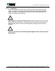
® ATD 50 Actuator Operating Instructions 1 Explanation of symbols This symbol warns of general hazards and of possible damage to the equipment. This symbol warns of dangerous electrical voltages or current 2 General Safety Instructions Before beginning installation or start-up, read and follow these instructions. Damage to the unit and personal injury may result from not following these instructions. Keep fingers away from all moving parts.
® ATD 50 Actuator Operating Instructions 2.1 Correct Use The ATD 50 Actuator® is designed for operating automatic doors on machine tools and industrial equipment. It is intended to automatically open and close doors, detect obstructions, and hold the door when closed. Vertical doors must be installed using a counter-weight system since the ATD 50 Actuator® is not intended to lift or hold the weight of a door. Any other use for the ATD 50 Actuator® is the judgement and risk of the installer.
® ATD 50 Actuator Operating Instructions 2.3 General Information (cont.) The purchaser, designer, and/or installer is responsible to insure the correct and safe application of the ATD 50 Actuator®. These personnel must insure that all Federal, State, and Local laws and regulations regarding workplace safety are observed. OSHA and other safety regulations must be observed when completing an installation.
® ATD 50 Actuator Operating Instructions 4 Design Information 4.1 Mechanical All components in the system must be designed and installed to withstand the forces produced by the system. This includes the door itself, all mounting brackets, the idler pulley, the connector between the door and belt, and the door end stops. Maximum tensile force of the belt Weight of the ATD 50 Actuator® unit 30 lbs (130 N) 31 lbs (14Kg) 4.1.1 The Door The door must have fixed positive stops at each end of travel.
® ATD 50 Actuator Operating Instructions 4.1.3 Installation The ATD 50 Actuator® internal frame is mounted into the metal enclosure with 6 screws. (There are two screws on the back of the unit and four button-head cap screws on the top.) For installation, only the four screws on the top OR the two screws on the back should be used. Never loosen all 6 screws at the same time! Otherwise the internal frame will be loose inside the metal housing.
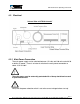
® ATD 50 Actuator Operating Instructions 4.2 Electrical Internal View of ATD 50 Actuator¨ 4.2.1 Main Power Connection The main power supply can be switched between 115 volts and 230 volts and with 50 or 60 Hz AC power. There is an internal switch on the main power connection to select 115V or 230V. The main power must be externally protected with a 10 amp fast-blow fuse and a system disconnect. Verify that the power selection switch is set to the correct voltage before start-up! Page 9 3811 N.
® ATD 50 Actuator Operating Instructions 4.2.2 Control Connection The ATD 50 Actuator® has a versatile microprocessor controller that interfaces with the machine control unit. The parameters are factory-set. However, a knowledgeable service technician can change the parameter settings using the Microsoft Windows ® ‘95 based SERsoft programming software. Inputs An input is activated when an input terminal (IN) is connected to ground (GND). This connection must be made using potential-free contacts.
® ATD 50 Actuator Operating Instructions 5.2 Start-up • • • • • • • Check the main power voltage selection switch for proper supply voltage (230V / 115V) Check the control connections and verify they are correctly installed Beware of Electrical Voltages! Switch on the main power supply to the drive. Start the calibration run (see section below). Check and test all functions to be used. If required, re-adjust door-specific parameters (opening and closing speeds, braking distance, etc.
® ATD 50 Actuator Operating Instructions 6 Check List for Functional Tests (cont.) TEST 3: ACTION: EXPECTED BEHAVIOR: TEST 4: ACTION: EXPECTED BEHAVIOR: OPTIMIZE MOVEMENTS Operate the door for two (2) complete open and close movements. Door should open and close normally. The microprocessor measures the torque and sets the internal speed and torque references. These references are used as safety thresholds for detecting obstructions.
® ATD 50 Actuator Operating Instructions 7 Error Diagnosis There are 10 error conditions that can be detected by installing LED’s to specific “B TERMINAL STRIP” outputs inside the ATD 50 Actuator®. The errors are indicated according to the following code: Software Error Number 2 3 9 10 11 12 13 16 29 30 Calibration run is taking place. Wait until door is closed for error to clear Main power failure. Microprocessor error or drive type not specified. Contact Factory. Emergency stop activated.
® ATD 50 Actuator Operating Instructions 8 Hardware Error Displays The microprocessor controller has a red and green LED light in the lower right corner. The LED lights indicate the general status of the microprocessor. GREEN LED The microprocessor controller is operating correctly.
® ATD 50 Actuator Operating Instructions 9 Standard Input Functions The ATD 50 Actuator® can accept either momentary or maintained contacts. The factory default is momentary. If additional safety requirements are desired, you can specify MAINTAINED CONTACT for the input signals. Maintained Contact Signals can be programmed in the Basic Functions Menu in the SERsoft programming software.
® ATD 50 Actuator Operating Instructions REDUCED OPEN This command causes the door to open to a preset position from the closed position only. Reason for use: Input terminal: Type of signal: Active level This command is used when a completely opened door is not required. (Operator may wish to access inside of machine briefly). C4 Momentary or maintained contact C4 to Ground A1. Connection is normally open. Close connection to activate.
® ATD 50 Actuator Operating Instructions SET REDUCED OPEN POSITION This command sets the reduced door open position. Reason for use: Input terminal: Type of signal: Active level The reduced open position can be manually set by using the input command at terminal F2. You must be able to manually move the door to the desired position before activating this input command. The distance can be set using the SERsoft programming software. F2 1 second contact of F2 to Ground F1. Connection is normally open.
® ATD 50 Actuator Operating Instructions REVERSING ERROR / GENERAL ERROR 2 This output is active when the internal and external reversing motions are initiated, usually due to an obstruction. (Error numbers 16, 29, or 30 active). Output terminal: E3 & E4 (Relay 2). Active level Contact is normally open (no error). Closed contact when activated (error present). DOOR POSITION IS CLOSED This output is active when the door is in the closed position ± 1/8 inch.
® ATD 50 Actuator Operating Instructions 11 Operation 11.1 Calibration Run The first movements after a power-up or system reset are the self-calibration reference moves. The door travels to each end-stop and records the distance traveled and torque needed for movement. The door can be freely moved before a Calibration Run. NOTE: The automatic reversing feature is disabled during the calibration cycles! The calibration cycle must be started by the external input signals. The calibration steps are: 1. 2. 3.
® ATD 50 Actuator Operating Instructions 11.2 Door Movements • • • • The input signals for OPEN, CLOSE and REDUCED OPEN can be given as momentary or maintained contacts. The door moves freely when in the open position. When open, the drive waits for the next input command signal. The door is locked with an internal brake ONLY when in the closed position. When closed, the door waits for the next input command.
® ATD 50 Actuator Operating Instructions 12 Memory and System Layout The heart of the ATD 50 Actuator® is a Motorola 68HC11 microprocessor. The microprocessor accesses an EPROM and EEPROM for specific software instructions and parameters. The general software instructions are stored in the EPROM. The application and door specific parameters are stored in the EEPROM. EPROM The universal operating software with general functions and instructions is stored in the EPROM.
® ATD 50 Actuator Operating Instructions 13 Technical data Connection Voltage 115 / 230V AC (selected with an internal switch) 50 / 60 Hz Power Consumption min. 4W max. 160 W Motor Nominal Speed 1600 rpm Motor Nominal Torque 9 inch- lbs (1 Nm) Maximum Drive Speed 443 rpm Maximum Tensile Force of Belt 30 lbs Maximum Drive Torque 32 inch- lbs (3.
® ATD 50 Actuator Operating Instructions Technical Data (cont.) OUTPUTS Relay: Contact load Contact protection Terminals Available Internal Power Supply Overload Protection 28VDC @ 1A or 120VAC @ 0.5A Must be externally connected. Required for inductive loads. RC-element for AC loads. Diode (1N4007) for DC load. E1 - 6 & I1 - 6. Refer to electrical wiring diagram. +24VDC 2.
® ATD 50 Actuator Operating Instructions 14 Electrical Wiring Diagram Page 24 3811 N. Holton Street • Milwaukee, WI • 53212 •USA • Phone • 414-906-4000 • Fax 414-906-4100 • www.MPCovers.
® ATD 50 Actuator Operating Instructions 15 Physical Dimensions Page 25 3811 N. Holton Street • Milwaukee, WI • 53212 •USA • Phone • 414-906-4000 • Fax 414-906-4100 • www.MPCovers.
ATD Actuator Troubleshooting Guide ® Symptom Door does not move Solutions 1) Check Power to Unit x Blown Supply Fuse supplying power to ATD x Power Cable plugged into selector switch inside x Selector switch set to correct voltage (115 or 230 VAC). If wrong voltage is selected the control or power module will be damaged! x Is the supply voltage too high or too low (+/- 10%) 2) Correct Wiring x Correct signals to correct wiring terminals x External wiring error from relay, pushbutton, etc.
Symptom Door does not move (continued) Solutions 2) Mechanically Related x Does the door move freely when connected to drive Belt? x No - Does the output sheave turn without excessive effort? (The sheave will require some effort to rotate. Sheave will not “spin”!) x No – loosen the four screws around the drive sheave up to 1 full turn. Turn output sheave by hand until sheave rotates freely. Retighten all four screws.
Symptom Door begins to close (or open) but reverses Door nearly fully closed (or open) but reverses Solutions 1) Mechanical Observations x Check door path for any obstructions such as large debris, chips, tool, “rough” spot in door track, etc.
Symptom ATD 50 does not sense an Obstruction Door “Slams or Runs Slow” against end stop Solutions 1) Sensitivity was changed from “High” to “Low” or “No”. 2) Change was made with SERsoft V1.2 to ATD 50 with EPROM T3197. Use SERsoft V1.5 to correct.