
User Manual

- 5 -
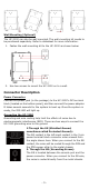
Wall Mounting (Optional)
The UC-3100 can also be wall mounted. The wall-mounting kit needs to
be purchased separately. Refer to datasheet for more information.
1. Fasten the wall-mounting kit to the UC-3100 as shown below:
2. Use two screws to mount the UC-3100 on to a wall.
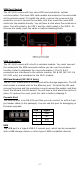
Connector Description
Power Connector
Connect the power jack (in the package) to the UC-3100’s DC terminal
block (located on the bottom panel), and then connect the power adapter.
It takes several seconds for the system to boot up. Once the system is
ready, the SYS LED will light up.
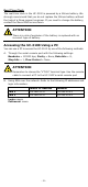
Grounding the UC-3100
Grounding and wire routing help limit the effects of noise due to
electromagnetic interference (EMI). There are two ways to connect the
UC-3100 grounding wire to the ground.
1.Through the SG (Shielded Ground,
sometimes called Protected Ground):
The SG co
ntact is the left-most contact in the 3-
pin
power terminal block connector when viewed from
the angle shown here. When you connect to the SG
contact, the noise will be routed through the PCB and
the PCB copper pillar to the metal chassis.
2. Through the GS (Grounding Screw):
The GS is located between the console port and the
power connector.
When you connect to the GS wire
,
the noise is routed directly from the metal chassis.