
Installation Guide

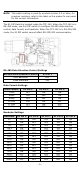
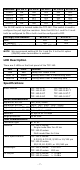

Table Of Contents

- 7 -
Baudrate
S1 Pin 5
S1 Pin 6
S1 Pin 7
S1 Pin 8
S1 Pin 9
57600
ON
ON
ON
ON
OFF
115200
OFF
ON
ON
ON
OFF
230400
ON
OFF
ON
ON
OFF
460800
OFF
OFF
ON
ON
OFF
921600
ON
ON
OFF
ON
OFF
The S2 DIP switch is located inside the TCF-142. This switch is used to
configure the pull high/low resistors. Note that S2 Pin 1 and Pin 2 must
both be configured to ON or both must be configured to OFF.
Pull High/Low Resistor
S2 Pin 1*
S2 Pin 2*
150K
OFF
OFF
1K (default)
ON
ON
* These DIP switches are located inside the TCF-142.
NOTE
We recommend setting S2 Pin 1 and Pin 2 to the 1K option
(ON/ON) when termination is enabled.
LED Description
There are 3 LEDs on the front panel of the TCF-142.
LED
Color
Function
PWR
Red
Steady ON: Power is ON
Fiber Tx
Green
Blinking when fiber is transmitting data
Fiber Rx
Orange
Blinking when fiber is receiving data
Specifications
Model Names
TCF-142-M-ST
TCF-142-M-SC
TCF-142-S-ST
TCF-142-S-SC
TCF-142-M-ST-T
TCF-142-M-SC-T
TCF-142-S-ST-T
TCF-142-S-SC-T
Serial Communication
Signals for RS-232
TxD, RxD, SGND
Signals for RS-422
TxD+, TxD-, RxD+, RxD-, SGND
Signals for 4-wire RS-485
TxD+, TxD-, RxD+, RxD-, SGND
Signals for 2-wire RS-485
Data+, Data-, SGND
Baudrate
50 bps to 921.6 kbps
Surge protection
15 kV ESD
Fiber Communication
Connector type
ST or SC
Distance TCF-142-S series:
Single mode fiber for 40 km
TCF-142-M series:
Multi mode fiber for 5 km
Cable Specifications TCF-142-S series:
8.3/125, 8.7/125, 9/125 or 10/125 μm
TCF-142-M series:
50/125, 62.5/125, or 100/140 μm
Wavelength
TCF-142-S series: 1310 nm
TCF-142-M series: 850 nm
TX Output
TCF-142-S series: > -5 dBm
TCF-142-M series: > -5 dBm