
User Manual

- 7 -
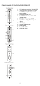
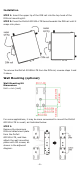
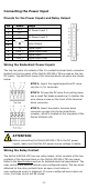
STEP 2:
Mounting the OnCell
G3150A-LTE
to a wall requires 4
screws. Use the OnCell
G3150A-LTE
device, with wall
mount plates attached as a guide, to mark the correct
locations of the 4 screws. The heads of the screws
should be less than 6.0 mm in diameter, and the
shafts
should be less than 3.5 mm in diameter, as shown in
the figure at the right.
NOTE
Test the screw head and shank size by inserting the screws into
one of the k
eyhole shaped apertures of the wall-mounting p
lates
before attaching the plates to the wall.
STEP 3:
Once the screws are fixed into the
wall, insert the four screw heads
through the large opening of the
keyhole
-shaped apertures, and
then slide the OnCell
G3150A-LTE
downwards, as indicated in the
accompanying diagram. Tighten
the four screws for added stability.
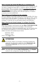
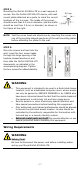
WARNING
•
This equipment is intended to be used in a Restricted Access
Location, such as a dedicated computer room, where a
ccess
can only be gained by SERVICE PERSONS or by USERS who
have been instructed about the
fact that the metal chassis of
the equipment is extremely hot and may cause burns.
•
Service persons or users should pay special attention and
take special precautions before handling this equipment.
•
Only authorized, well-trained professionals should be allo
wed
to access the restricted access location. Access should be
controlled by the authority responsible for the location with
lock and key or a security identity system.
•
External metal parts are hot!!
Pay special attention or use
special protection before handling this equipment.
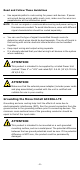
Wiring Requirements
WARNING
Safety First!
Be sure to disconnect the power cord before installing and/or
wiring your Moxa OnCell G3150A-LTE.