
User Manual

- 11 -
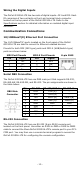
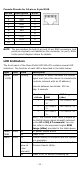
Console Pinouts for 10-pin or 8-pin RJ45
10-Pin
Description
8-Pin
1
–
2
DSR
1
3
RTS
2
4
GND
3
5
TxD
4
6
RxD
5
7
–
6
8
CTS
7
9
DTR
8
10
–
NOTE
The pin numbers for both 8
-pin and 10-
pin RJ45 connectors (and
ports) are typically not labeled on the connector (or port). Refer
to the pinout diagram above for details.
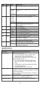
LED Indicators
The front panel of the Moxa OnCell G3150A-LTE contains several LED
indicators. The function of each LED is described in the table below:
Type
Color
State
Description
Signal
(1 LED)
Green
Blinking
The number of blinks indicates the cellular
signal level (once the device is
connected to
a cellular network with an IP address.)
Interval between two blinks: 200 ms
Gap: 2 seconds
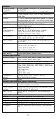
Number
of Blinks
Cellular
RSSI
RSSI Range
(dBm)
1
0 < SNR ≤
12
113 < RSSI ≤ -89
2 12 < SNR ≤
21
-89 < RSSI ≤ -73
3 22 < SNR ≤
31
-73 < RSSI ≤ -51
NOTE: The Cellular RSSI value is based on
the OnCell device signal strength returned
by the AT+ CSQ AT command. You can
also refer to the equivalent signal RSSI
Range (dBm) provided in the table above.
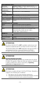
PWR1/
PWR2
Green
On
DC power source active
Off
Power is off
Ready
Green
On
System startup is complete and the system
is in operation.
Blinking
(slow at
1-sec
intervals)
The OnCell device has been located by the
Wireless Search Utility.
Off
Power is off, or device is booting up.