OnCell G3150A-LTE Quick Installation Guide Moxa OnCell Series Edition 2.0, August 2017 Technical Support Contact Information www.moxa.
Overview The OnCell G3150A-LTE is a reliable, secure, LTE gateway with state-of-the-art global LTE module. This 4G cellular gateway provides a more reliable connection to your Ethernet network for cellular applications. To enhance industrial reliability, the OnCell G3150A-LTE features isolated power inputs, which together with high-level EMS and wide-temperature support give the OnCell G3150A-LTE the highest level of device stability for any rugged environment.
Step 2: Connect the OnCell G3150A-LTE to a notebook or PC Since the OnCell G3150A-LTE supports MDI/MDI-X auto-sensing, you can use either a straight-through cable or crossover cable to connect the OnCell G3150A-LTE to a computer. See the 10/100BaseT(X) Ethernet Port Connection section below for detailed instructions. If the LED indicator on the OnCell G3150A-LTE’s LAN port lights up, it means a connection has been established.
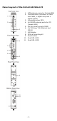
Panel Layout of the OnCell G3150A-LTE 1. 2. 3. 4. 5. 6. 7. 8. 9. 10. 11.
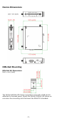
Device Dimensions DIN-Rail Mounting DIN-Rail Kit Dimensions Unit = mm (inch) The OnCell G3150A-LTE Series computers come with a DIN-rail kit attached to the back panel. Mount the OnCell G3150A-LTE Series on corrosion-free mounting rails that meet the EN 60715 standard.
Installation STEP 1: Insert the upper lip of the DIN rail into the top hook of the DIN-rail mounting kit. STEP 2: Press the OnCell G3150A-LTE Series towards the DIN rail until it snaps into place. To remove the OnCell G3150A-LTE from the DIN rail, reverse steps 1 and 2 above.
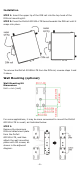
STEP 2: Mounting the OnCell G3150A-LTE to a wall requires 4 screws. Use the OnCell G3150A-LTE device, with wall mount plates attached as a guide, to mark the correct locations of the 4 screws. The heads of the screws should be less than 6.0 mm in diameter, and the shafts should be less than 3.5 mm in diameter, as shown in the figure at the right.
Read and Follow These Guidelines • Use separate paths to route wiring for power and devices. If power wiring and device wiring paths must cross, make sure the wires are perpendicular at the intersection point. NOTE Do not run signal or communications wiring and power wiring in the same wire conduit. To avoid interference, wires with different signal characteristics should be routed separately.
Connecting the Power Input Pinouts for the Power Inputs and Relay Output Pin 1 2 3 4 5 6 7 8 9 10 Name V1+ V1V2+ V2- Usage DC Power Input 1 DC Power Input 2 Relay Output I1 COM_1 I2 COM_2 Digital Digital Digital Digital Input Input GND Input Input GND Wiring the Redundant Power Inputs The top two pairs of contacts of the 10-contact terminal block connector located on the top panel of the OnCell G3150A-LTE are used as the two DC inputs.
Wiring the Digital Inputs The OnCell G3150A-LTE has two sets of digital inputs—DI1 and DI2. Each DI comprises of two contacts on the 6-pin terminal block connector located on the top panel of the OnCell G3150A-LTE. Refer to the Specifications section for detailed information on isolated digital input definition. Communication Connections 10/100BaseT(X) Ethernet Port Connection The 10/100BaseT(X) ports located on the front panel of the OnCell G3150A-LTE are used to connect to Ethernet-enabled devices.
Console Pinouts for 10-pin or 8-pin RJ45 10-Pin 1 2 3 4 5 6 7 8 9 10 Description – DSR RTS GND TxD RxD – CTS DTR – 8-Pin 1 2 3 4 5 6 7 8 NOTE The pin numbers for both 8-pin and 10-pin RJ45 connectors (and ports) are typically not labeled on the connector (or port). Refer to the pinout diagram above for details. LED Indicators The front panel of the Moxa OnCell G3150A-LTE contains several LED indicators.
Type Color State Description Fault Red On Device is booting up, or IP address conflict. Blinking (slow at 1-sec intervals) Off Cannot get an IP address from the DHCP server Power is off or no error condition exists. 2G / 3G Amber Blinking (slow at 500-ms intervals) On Off GSM/GPRS/EDGE is connected. 4G Amber On Off LTE is connected LTE is disconnected.
Interface Cellular Antenna Connectors SIM Slots GNSS 2 SMA (female), MIMO for LTE, antenna diversity for WCDMA Dual SIM card support, full-sized SIM (1FF) 1 SMA (female), GPS: 1575.42 MHz, GLONASS: 1602 MHz Ethernet 1, 10/100 Mbps auto negotiation speed, F/H duplex mode and auto MDI/MDI-X connection (RJ45-type) Serial Console Port 1, RS-232 (RJ45-type) Serial Port 1, RS-232, RS-485-4W , RS-485-2W, RS-422 (DB9 male) Serial Data Bits: 5,6,7,8 Communication Stop Bits: 1,1.
Environmental Limits Operating Standard Models: 0 to 55°C (32 to 131°F) Temperature Wide Temp. Models: -30 to 70°C (-22 to 158°F) Storage -40 to 85°C (-40 to 185°F) Temperature Ambient Relative 5 to 95% (30°C, non-condensing) Humidity Power Requirements Input Voltage 12 to 48 VDC, redundant dual DC power inputs Connector 4-pin removable terminal block Power Consumption 9.6 W (12 V/0.78 A to 48 V/0.
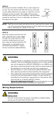
ATTENTION Do not locate the antenna near overhead power lines or other electric light or power circuits, or where it can come into contact with such circuits. When installing the antenna, take extreme care not to come into contact with such circuits, because they may cause serious injury or death when there is a surge. For instructions on proper installation and grounding of the antenna, refer to national and local codes (for example, U.S.
Grounding-Wire Size The minimum cross-sectional area of the grounding conductor should be equal to that of the input cable. Moxa Inc. 4th Floor, No.135, Lane 235, Baoqiao Rd. Xindian Dist.