
User`s manual


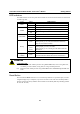


Table Of Contents
- 1. Introduction
- 2. Getting Started
- 3. Initial IP Address Configuration
- 4. Introducing Serial Port Operation Modes
- 5. Introducing OnCell Central and Ethernet Operation Modes
- 6. Using the Web Console
- 7. Cellular Network Settings
- 8. Configuring Serial Port Operation Modes
- 9. Configuring the Cellular-Enabling Ethernet Device
- 10. Configuring OnCell Central Management Software
- 11. Additional Serial Port Settings
- 12. System Management Settings
- 13. Software Installation/Configuration
- A. Pinouts and Cable Wiring
- B. RFC2217
- C. Dynamic Domain Name Server
- D. Well Known Port Numbers
- E. Auto IP Report Protocol
- F. GSM Alphabet
- G. Default Settings

OnCell G3111/G3151/G3211/G3251 Series User’s Manual Getting Started
2-6
Connecting to the Network
Connect one end of the Ethernet cable to the OnCell G3111/G3151/G3211/G3251’s 10/100M
Ethernet port and the other end of the cable to the Ethernet network.
If the cable is properly connected, the OnCell G3111/G3151/G3211/G3251 will indicate a valid
connection to the Ethernet as follows:
The Ethernet LED glows a solid green when connected to a 100 Mbps Ethernet network.
The Ethernet LED glows a solid orange when connected to a 10 Mbps Ethernet network.
The Ethernet LED flashes when Ethernet packets are being transmitted or received.
Connecting to a Serial Device
The OnCell G3111 and G3211 support one or two RS-232 port that connects through a DB9 male
connector on the bottom panel.
The OnCell G3151 and G3251 support one or two RS-232/RS-422/RS-485-4w/RS-485-2w port
that connects through a DB9 male connector on the bottom panel.
Adjustable Pull High/Low Resistors for the RS-485 Port (G3151/G3251)
In some critical environments, you may need to add termination resistors to prevent the reflection of
serial signals. When using termination resistors, it is important to set the pull high/low resistors
correctly so that the electrical signal is not corrupted. Since a particular pull high/low resistor value
cannot fit all environments, the OnCell G3151/G3251 uses DIP switches to set the pull high/low
resistor values for the serial port.
To set the termination resistor to 150 KΩ, make sure both of the assigned DIP switches are in the
OFF position. This is the default setting.
To set the termination resistor to 1 KΩ, make sure both of the assigned DIP switches are in the
ON position.
ATTENTION
Do not use the 1 KΩ setting on the OnCell G3151/G3251 when using the RS-232 interface.
Doing so will degrade the RS-232 signals and shorten the maximum allowed communication
distance.
DIP switches on the bottom of the OnCell G3111/G3151/G3211/G3251 are used to set the pull
high/low resistor value for each serial port.
SW
1
2
3
4
Pull High
Pull Low
Terminator
---
ON
1 KΩ
1 KΩ
120 KΩ
---
OFF
150 K
Ω
150 K
Ω
---
---
Note: If the pull high/low resistor on your device is already set for RS-485, make sure the
default SW for RS-232 is “OFF” when you switch back to RS-232 interface.