
User Manual
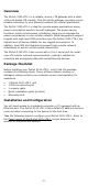
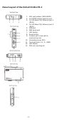
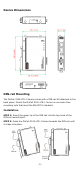
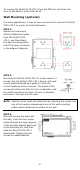
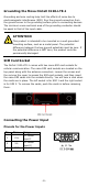
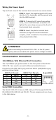
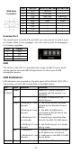
Table Of Contents
- OnCell 3120-LTE-1 Quick Installation Guide
- Overview
- Package Checklist
- Installation and Configuration
- Panel Layout of the OnCell 3120-LTE-1
- Device Dimensions
- DIN-rail Mounting
- Wall Mounting (optional)
- Wiring Requirements
- Grounding the Moxa OnCell 3120-LTE-1
- SIM Card Socket
- Connecting the Power Input
- Communication Connections
- LED Indicators
- Specifications
- ATEX / IECEx Zone 2 Certification Information
- Grounding-wire Size
- 6 -
To remove the OnCell 3120-LTE-1 from the DIN rail, pull down the
lever at the bottom of the DIN-rail kit.
Wall Mounting (optional)
For some applications, it may be more convenient to mount the OnCell
3120-LTE-1 to a wall, as illustrated below:
STEP 1:
Remove the aluminum
DIN
-
rail attachment plate
from the OnCell
3120-
LTE
-1, and then attach
the wall
-mounting plates
with M3 screws, as shown
in the adjacent diagram.
STEP 2:
Mounting the OnCell
3120-LTE-1 to a wall requires 4
screws. Use the
OnCell 3120-LTE-1 device, with wall
mount plates attached as a guide, to mark the
correct locations of the 4 screws. The heads of the
screws should be less than 6.0 mm in diameter, and
the
shafts should be less than 3.5 mm in diameter,
as shown in the figure at the right.
NOTE
Test the screw head and shank size by inserting the screws into
one of the k
eyhole shaped apertures of the wall-mounting
plates before attaching the plates to the wall.
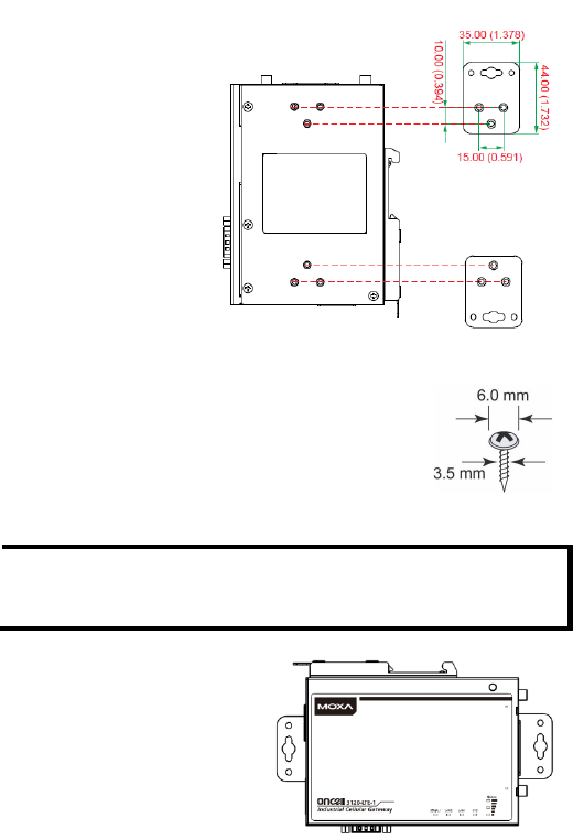
STEP 3:
Once the screws are fixed into
the wall, insert
the four screw
heads through the large opening
of the keyhole
-shaped apertures
of the mounting kit
, and then
slide the OnCell
3120-LTE-1
downwards. Tighten the four
screws for added stability.