
User Manual
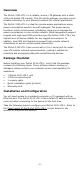
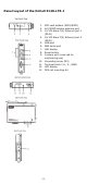
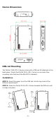
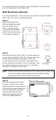
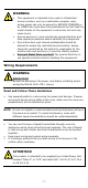
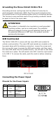
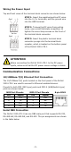
Table Of Contents
- OnCell 3120-LTE-1 Quick Installation Guide
- Overview
- Package Checklist
- Installation and Configuration
- Panel Layout of the OnCell 3120-LTE-1
- Device Dimensions
- DIN-rail Mounting
- Wall Mounting (optional)
- Wiring Requirements
- Grounding the Moxa OnCell 3120-LTE-1
- SIM Card Socket
- Connecting the Power Input
- Communication Connections
- LED Indicators
- Specifications
- ATEX / IECEx Zone 2 Certification Information
- Grounding-wire Size
- 4 -
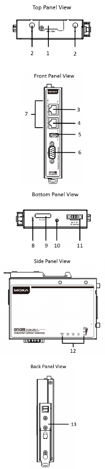
Panel Layout of the OnCell 3120-LTE-1
1. SIM card holders (SIM1/SIM2)
2. 2x2 MIMO cellular antenna port
3. 10/100 Base-T(X) Ethernet port 1
(RJ45)
4. 10/100 Base-T(X) Ethernet port 2
(RJ45)
5. USB port
6. DB9 serial port
7. LED display
8. Reset button
9. Console port (reserved for
engineering use)
10.
Grounding screw (M3)
11.
Terminal block (V+, V-, GND)
12.
LED display
13.
DIN-rail mounting kit