
User Manual
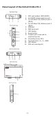
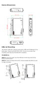
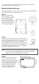
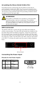
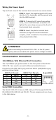
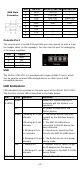
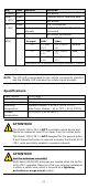
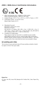
Table Of Contents
- OnCell 3120-LTE-1 Quick Installation Guide
- Overview
- Package Checklist
- Installation and Configuration
- Panel Layout of the OnCell 3120-LTE-1
- Device Dimensions
- DIN-rail Mounting
- Wall Mounting (optional)
- Wiring Requirements
- Grounding the Moxa OnCell 3120-LTE-1
- SIM Card Socket
- Connecting the Power Input
- Communication Connections
- LED Indicators
- Specifications
- ATEX / IECEx Zone 2 Certification Information
- Grounding-wire Size
- 11 -
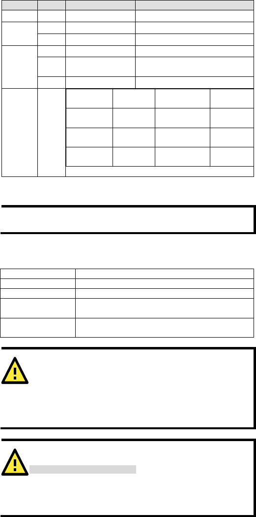
LED
Color
Behavior
Function
(4 LEDs)
Off
Not active.
Serial
(2 LEDs)
Green
Transmitting or receiving data.
Off
Not active.
LTE
(1 LED)
Green
LTE is connected.
Green
Blinking at 0.5-sec
intervals
UMTS/HSPA/GSM/GPRS/EDGE is
connected.
Off
No cellular connection.
Signal (3
LEDs)
Green
Signal
Strength*
Cellular
RSSI
RSSI Range
(dBm)
Comment
1-2 0 < SNR
≤ 12
113 < RSSI ≤
-89
Marginal
3-4 12 < SNR
≤ 21
-89 < RSSI ≤
-73
Good
5-6 22 < SNR
≤ 31
-73 < RSSI ≤
-51
Excellent
*Each signal LED is equivalent to a signal strength of 2 levels.
NOTE
The LTE LED is designated for the cellular connectivity standard
and the SIGNAL LED indicates the cellular signal strength.
Specifications
Input Current
0.8 A (max.)
Input Voltage
9 to 36 VDC
Power Consumption
5 W (typ.)
Operating
Temperature
Standard Models: 0 to 55°C (32 to 131°F)
Wide Temp. Models: -30 to 70°C (-22 to 158°F)
Storage
Temperature
-40 to 85°C (-40 to 185°F)
ATTENTION
The OnCell
3120-LTE-1 is NOT a portable mobile device and
should be located at least
20 cm away from the human body.
The OnCell
3120-LTE-1 is NOT designed for the general pu
blic.
A well
-trained technician is required to deploy the OnCell 3120-
LTE-1 units and safely establish a wireless network.
ATTENTION
Use the antennas correctly!
Wide
-band (2G/3G/4G) antennas are needed when the OnCell
3120
-LTE-1 operates. Make sure that your antenna installation
is within a safety area, which is covered by a
lightning
protection or surge arrest system.