
User Manual
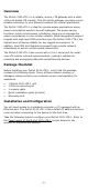
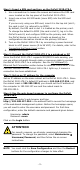
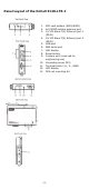
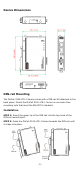
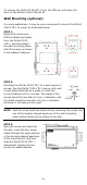
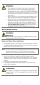
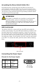
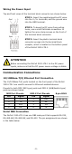
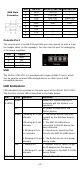
Table Of Contents
- OnCell 3120-LTE-1 Quick Installation Guide
- Overview
- Package Checklist
- Installation and Configuration
- Panel Layout of the OnCell 3120-LTE-1
- Device Dimensions
- DIN-rail Mounting
- Wall Mounting (optional)
- Wiring Requirements
- Grounding the Moxa OnCell 3120-LTE-1
- SIM Card Socket
- Connecting the Power Input
- Communication Connections
- LED Indicators
- Specifications
- ATEX / IECEx Zone 2 Certification Information
- Grounding-wire Size
- 10 -
DB9 Male
Connector
Pin
RS-232
RS-422/485-4w
RS-485-2w
1
DCD
TxD-(A)
–
2
RxD
TxD+(B)
–
3
TxD
RxD+(B)
Data+(B)
4
DTR
RxD-(A)
Data-(A)
5
GND
GND
GND
6
DSR
–
–
7
TRS
–
–
8
CTS
–
–
9
–
–
–
Console Port
The console port is an RS-232 port that you can connect to with a 4-pin
pin header cable (in the package). You can use this port for debugging
or firmware upgrades.
Pin
Signal
1
GND
2
NC
3
RxD
4
TxD
USB
The OnCell 3120-LTE-1 is provided with a type-A USB 2.0 port, which
can be used to connect USB storage device or other type-A USB
compatible devices.
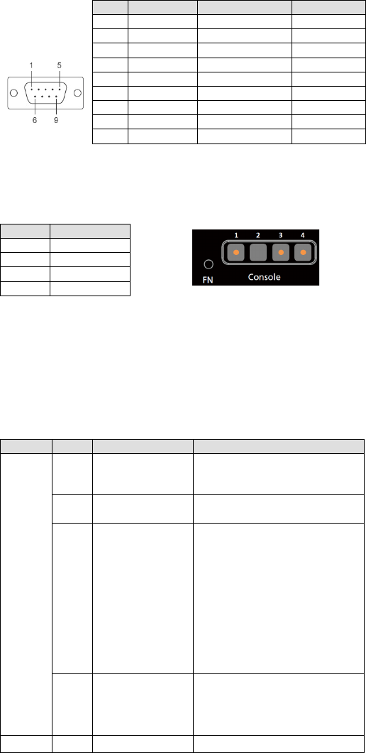
LED Indicators
LED indicators are provided on the side panel of the OnCell 3120-LTE-1.
The function of each LED is described in the table below:
LED
Color
Behavior
Function
SYS
(2 LEDs)
Green
Power On: System startup is
complete and the system is in
operation.
Off
No power is supplied to the
OnCell device.
Green
1.Blinking at 1-sec
interval
s
2.Blinking at 2
-sec
intervals
3. Blinking at 0.5
-
sec intervals
4.
Blinking at 5-
sec
intervals
1. The OnCell device has been
located by the Wireless Search
Utility.
2. The ABC-02-USB device
connected to OnCell device has
been detected.
3. Importing or exporting files
from/to the ABC-02-USB device.
4. The OnCell device is in power
saving mode.
Red
1. Steady On
2. Blinking at
1-sec
intervals
1. System error or failure to get
an IP address for the device.
2. Load/save to the ABC-02-USB
device failed.
LAN 1/2
Green
10/100 Mbps Ethernet mode.