OnCell 3120-LTE-1 Quick Installation Guide Moxa OnCell Series Version 1.0, October 2019 Technical Support Contact Information www.moxa.
Overview The OnCell 3120-LTE-1 is a reliable, secure, LTE gateway with a stateof-the-art global LTE module. This 4G cellular gateway provides a more reliable connection to your Ethernet network for cellular applications. The OnCell 3120-LTE-1 is ideal for remote-access applications where power consumption needs to be well managed. The power-saving functions, which include power scheduling, allow you to manage the power consumption in your cellular network.
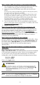
Step 1: Insert a SIM card and turn on the OnCell 3120-LTE-1 1. Use a screwdriver to loosen the screws and remove the SIM card cover located on the top panel of the OnCell 3120-LTE-1. 2. Insert one or two 4G SIM cards (nano SIM) into the SIM card slot(s). If you are only using one SIM card, insert it in the top slot (slot 1; the card in slot 1 is referred to as SIM1). By default, the SIM card in slot 1 is treated as the primary card.
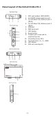
Panel Layout of the OnCell 3120-LTE-1 1. 2. 3. 4. 5. 6. 7. 8. 9. 10. 11. 12. 13.
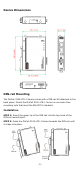
Device Dimensions DIN-rail Mounting The OnCell 3120-LTE-1 Series comes with a DIN-rail kit attached to the back panel. Mount the OnCell 3120-LTE-1 Series on corrosion-free mounting rails that meet the EN 60715 standard. Installation STEP 1: Insert the upper lip of the DIN rail into the top hook of the DIN-rail mounting kit. STEP 2: Press the OnCell 3120-LTE-1 Series towards the DIN rail until it snaps into place.
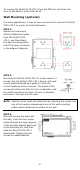
To remove the OnCell 3120-LTE-1 from the DIN rail, pull down the lever at the bottom of the DIN-rail kit. Wall Mounting (optional) For some applications, it may be more convenient to mount the OnCell 3120-LTE-1 to a wall, as illustrated below: STEP 1: Remove the aluminum DIN-rail attachment plate from the OnCell 3120LTE-1, and then attach the wall-mounting plates with M3 screws, as shown in the adjacent diagram. STEP 2: Mounting the OnCell 3120-LTE-1 to a wall requires 4 screws.
WARNING • • • • This equipment is intended to be used in a Restricted Access Location, such as a dedicated computer room, where access can only be gained by SERVICE PERSONS or by USERS who have been instructed about the fact that the metal chassis of the equipment is extremely hot and may cause burns. Service persons or users should pay special attention and take special precautions before handling this equipment.
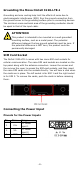
Grounding the Moxa OnCell 3120-LTE-1 Grounding and wire routing help limit the effects of noise due to electromagnetic interference (EMI). Run the ground connection from the ground screw to the grounding surface prior to connecting devices. The minimum cross-sectional area of the grounding conductor should be equal to that of the input cable. ATTENTION This product is intended to be mounted on a well-grounded mounting surface, such as a metal panel.
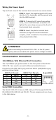
Wiring the Power Input Top and front views of the terminal block connector are shown below: STEP 1: Insert the negative/positive DC wires into the V-/V+ terminals, and the ground wire into the GND terminal. STEP 2: To keep the DC wires from pulling loose, use a small flat-blade screwdriver to tighten the wire-clamp screws on the front of the terminal block connector.
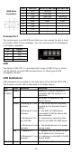
DB9 Male Connector Pin 1 2 3 4 5 6 7 8 9 RS-232 DCD RxD TxD DTR GND DSR TRS CTS – RS-422/485-4w RS-485-2w TxD-(A) – TxD+(B) – RxD+(B) Data+(B) RxD-(A) Data-(A) GND GND – – – – – – – – Console Port The console port is an RS-232 port that you can connect to with a 4-pin pin header cable (in the package). You can use this port for debugging or firmware upgrades. Pin 1 2 3 4 Signal GND NC RxD TxD USB The OnCell 3120-LTE-1 is provided with a type-A USB 2.
LED Color Behavior (4 LEDs) Off Function Not active. Serial Green (2 LEDs) Off Transmitting or receiving data. LTE (1 LED) LTE is connected. Not active. Green Green Blinking at 0.5-sec UMTS/HSPA/GSM/GPRS/EDGE is intervals connected. Off No cellular connection.
ATTENTION This device complies with part 15 of the FCC Rules. Operation is subject to the following two conditions: 1. 2. This device may not cause harmful interference. This device must accept any interference received, including interference that may cause undesired operation. ATTENTION Do not locate the antenna near overhead power lines or other electric light or power circuits, or where it can come into contact with such circuits.
ATEX / IECEx Zone 2 Certification Information . 1. 2. 3. 4. 5. ATEX Certificate Number: DEMKO 18 ATEX 2120X IECEx Certificate Number: IECEx UL 18.0113X Ambient Range:-30°C ≤ Ta ≤ +70°C, or -30°C ≤ Tamb ≤ +70°C Certification String : Ex nA IIC T4 Gc Rated Cable Temp ≧ 90 °C Standards Covered: EN 60079-0:2012+A11:2013 EN 60079-15:2010 IEC 60079-0, 6th Edition (2011-06) + Corr. 1 (2012-01) + Corr.