
User Manual

- 5 -
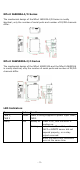
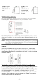
STEP 1:
Insert
the top of the
DIN rail into the
slot.
STEP 2:
The
DIN rail
attachment unit
will snap into
place as shown
at right.
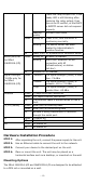
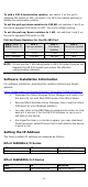
Wall Mounting (optional)
For some applications, it may be more convenient to mount the NPort
IA5000A-I/O or IAW5000A-I/O to a wall, as illustrated below.
Do not drive the screws in all the way—leave a space of about 2 mm to
allow room for sliding the wall-mounting panel between the wall and the
screws.
NOTE
Test the screw head and shank size by inserting the screws into
one of the keyhole
-shaped apertures of the wall-
mounting plates
before they are fixed to the wall.
STEP 3:
Once the screws are fixed into the wall, insert the four screw heads
through the large opening of the keyhole-shaped apertures, and then
slide the NPort downwards, as indicated to the right. Tighten the screws
for added stability.
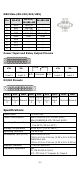
Termination Resistor and Adjustable Pull-Up/Down Resistors
In some critical environments, you may need to add termination resistors
to prevent the reflection of serial signals. When using termination
resistors, it is important to set the pull-up/down resistors correctly so that
the electrical signal is not corrupted. The NPort IA5000A-I/O and
IAW5000A-I/O Series use DIP switches to set the pull-up/down resistor
values for each serial port. The DIP switches are located at the side of
wireless device server for easy setting.